
User manual


Installing and Maintaining the Versalar Switch Router 15000
3-26
308684-B Rev 00
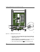
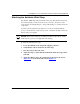
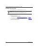
Figure 3-15. AC Management Cable Location
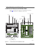
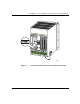
7.
Insert the power plugs on the back of the separate AC power unit into the
appropriate power outlet. (See Table 2-5 on page 2-8). Each power supply
requires one power cord.
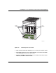
8.
Turn the AC POWER A and AC POWER B power breakers on the front
panel of the separate AC power unit to the on (1) position.
9.
Turn on the DC output switch on the right side of the unit front panel.
VR
S
External AC power supply
AC
management
cable
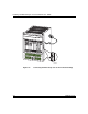
SW1
Grounding
stud
Groundi
n
wire