
User's Manual


Chapter 3 Viewing the BCM system LEDs 81
BCM200/400 4.0 Installation and Maintenance Guide
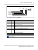
Figure 47 DTM LEDs
Table 21 describes the functions of the DTM LEDs.
Table 21 DTM LED functions
LED Status Descriptions
Power – Refer to “Media bay module LEDs” for details.
Status – Refer to “Media bay module LEDs” for details.
In service Flashing The T1, ETSI, or PRI trunks are out of service because a loopback test is
running or the DTM is initializing.
Loopback test On A continuity loopback test is running.
Receive alarm On A problem with the received digital transmission. This half-duplex link does
not work.
Receive error On A small error as a result of degraded digital transmission. Possible causes are
an ohmic connection, water ingress, or too long a loop.
Transmit alarm On The DTM cannot transmit. The DTM sends an alarm indication signal (AIS) to
the terminating switch. This half-duplex link does not work.
Transmit error On The DTM is sending a remote alarm indication (RAI) carrier failure alarm
(CFA) to the terminating switch. If the transmit alarm is not on, this error
indicates a far-end or cable problem.
All LEDs Flashing The DTM is initializing.
Tip: You can install a maximum of three DTM modules in the BCM main unit, depending
on the available buses.
Power LED
Status LED
In service LED
Loopback test LED
Receive LEDs
Transmit LEDs