
User's Manual


Chapter 3 Viewing the BCM system LEDs 79
BCM200/400 4.0 Installation and Maintenance Guide
During system startup, the power LED and the status LED indicate the status of the system.
Table 19 describes the various states of the Power and Status LEDs, and the corresponding alarm
conditions during system startup.
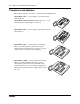
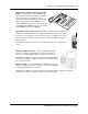
Media bay module LEDs
The two media bay module (MBM) LEDs show the power and status of the MBM. Figure 46
shows the location of the
(Power) and (Status) LEDs on an MBM. The power and status
LEDs are located in the same place on all MBMs.
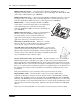
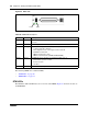
Temp Monitors the main unit and CPU temperature. Green ON – normal
Red ON – sensor is non-operational or temperature
is out of range.
Note: Red LED indicates a possible fan failure.
Fan Monitors the status of the fans. Green ON – all installed fans are working
Red ON – sensor failure or there is a problem with
at least one fan
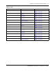
Table 19 Power and Status LED states and descriptions during system startup
Power LED Status LED Description
Solid Green Solid Green Non alarm condition - Normal operation
Solid Red Solid Green Alarm condition - Normal operation
Solid Green Off Alarm condition - Startup profile
Solid Red Off LED state 5
Alarm 10906: System Startup - Operating system and alarm subsystem
available
Solid Red Blinking Green LED state 6
Alarm 10907: System Startup - Telephony and voice mail active
Solid Green Blinking Green LED state 7
Alarm 10908: System Startup - Element Manager is available
Solid Green Solid Green LED state 8
Alarm 10909: System Startup - Startup complete. Service Manager and
Scheduling Services available
Table 18 Base function tray system status LED states (Sheet 3 of 3)
LED Description LED states