
User's Manual


Chapter 3 Viewing the BCM system LEDs 77
BCM200/400 4.0 Installation and Maintenance Guide
Chapter 3
Viewing the BCM system LEDs
Refer to the following sections for information on the BCM system LEDs:
• “Base function tray system status display LEDs”
• “Media bay module LEDs” on page 79
Base function tray system status display LEDs
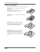
A line of 10 LEDs displays on the base function tray faceplate of the BCM main unit (see Figure
45 and Table 18). The LEDs show the current state of various hardware components. Element
Manager contains a monitoring tool that allows you to determine the current condition of the LEDs
from your computer.
Figure 45 BCM base function tray system status LEDs
Table 18 summarizes the possible operating states of the LEDs on the front of the base function
tray. The BCM expansion unit has both a power and a status LED, which provide the same
indicators as for the base function tray.
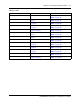
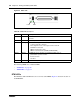
Table 18 Base function tray system status LED states (Sheet 1 of 3)
LED Description LED states
Power Indicates the status of all power components.
The Power LED is used with the Status LED to show
startup conditions (see Table 19
).
An LED that monitors a component will also show a
fault in combination with the Power LED.
Green ON – normal operation
Red ON – an excessive voltage deficiency or a
component failure (such as a redundant power
supply module)
Disk Indicates access to the system hard disk. Green ON – hard disk activity detected
This LED lights when the HDD is accessed. If the
systems does not need to read or write to the HDD
the LED is off.
Power StatusDisk Temp FanMSC
WAN
Modem
LAN 1
LAN 2
Red or Green