
User's Manual


Chapter 2 Introducing the BCM hardware 57
BCM200/400 4.0 Installation and Maintenance Guide
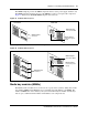
Digital station media bay module
The digital station media bay modules (DSM) support digital telephones on the BCM system. This
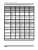
section describes the DSM16(+) and DSM32(+) MBMs (see Figure 31).
The DSMs have the following characteristics:
• DSM16(+) — supports 16 digital telephones through one RJ-21 connector. Set the double
density switch to enable the DSM to carry 16 extensions over a half DS30 bus. If required,
install a second DSM16(+) and set the double density switch to occupy the second half of the
DS30 bus to expand the number of extensions to 32.
• DSM32(+) — supports 32 digital telephones through two RJ-21 connectors. A DSM32(+)
operating in single-density mode occupies two DS30 buses. Set the double density switch to
enable the DSM to carry 32 extensions over a single DS30 bus.
Figure 31 DSM faceplate LEDs and connectors
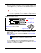
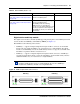
ASM/ASM8
(see “Analog station media bay modules”
on page 58)
Connects a maximum of eight analog
devices to the BCM system.
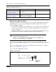
ASM8+/GASM
(see “Analog station media bay modules”
on page 58)
Connects a maximum of eight analog
devices to the BCM system.
The GASM provides the following
additional services: caller ID, pass
through, message waiting indication, and
disconnect supervision at the telephone.
The GASM also allows you to download
new firmware.
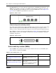
Note: Refer to “Market profile attributes” on page 351 for supported regions.
Note: Devices that share a DS30 bus must be similar. Use two DSM16(+)
module in double density mode on a single DS30 bus. Do not mix a DSM16(+)
module with a DSM32(+) module over a single DS30 bus.
Table 9 Station MBMs (Sheet 2 of 2)
MBM What it does Special notes
DSM 32(+)
DSM 16(+)