
User's Manual


Chapter 2 Introducing the BCM hardware 51
BCM200/400 4.0 Installation and Maintenance Guide
The MBM backplane provides the MBM component interface to the power supply and main card.
The MBM backplane mounts at the rear of the MBM bays and is a non-replaceable component.
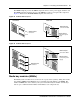
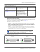
Figure 23 illustrates the BCM200 MBM backplane and connectors.
Figure 23 BCM200 MBM backplane
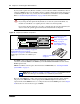
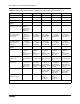
Figure 24 illustrates the BCM400 MBM backplane and connectors.
Figure 24 BCM400 MBM backplane
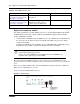
Media bay modules (MBMs)
The BCM system is modular. You can increase the capacity of the system by adding more media
bay modules (MBMs). Each BCM allocates a maximum of six DS30 buses to the MBMs. The
number of MBMs that can be added to your system is determined by the number of media bays
that are open, combined with the number of DS30 buses each component uses.
MBM backplane
connectors
Front view Rear view
MBM backplane
connector to MSC
MBM backplane
connector to power
supply
Front view
MBM backplane
connector to MSC
MBM backplane
connector to power
supply
MBM backplane
connectors
Rear view