
User's Manual


48 Chapter 2 Introducing the BCM hardware
N0060612N0060612
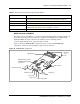
Modem card
The V.92 (or V.90) modem connects the BCM system to the public switched telephone network
(PSTN), enabling the BCM system to send and receive data. The modem card is standard on North
American systems, while it is optional for APAC and EMEA. The modem kit consists of a modem
card, RJ-11 interface, and connector cable. For further information on installation and removal, see
“To install a modem card” on page 309 and “To remove the modem card” on page 307.
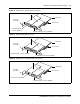
Figure 19 shows the modem components.
Use the modem connection to:
• manage the BCM system from a different location
• provide dial-up backup for a WAN card
Figure 19 Modem card and interface
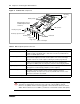
I/O interface card
The I/O interface card provides a signal junction between the base function tray, hard disk, power
supply, and cooling system. Figure 20 shows the I/O interface card and connections.
Main card connector
RJ-11 connector
(exposed on base
function tray face)
2-pin connector
To main card modem
socket connector
Base function tray
mount points
Modem card
pin guide
Modem card RJ-11 card interface