
User's Manual


Chapter 2 Introducing the BCM hardware 39
BCM200/400 4.0 Installation and Maintenance Guide
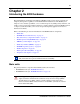
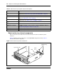
Figure 7 Advanced function tray RAID status LEDs
Base function tray component hardware
This section describes the following base function tray components:
• “Base function tray faceplate components” on page 39
• “Base function tray internal components” on page 40
• “Main card” on page 43
• “Data networking components” on page 46
• “I/O interface card” on page 48
Base function tray faceplate components
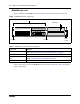
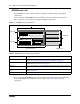
Figure 8 illustrates the base function tray faceplate components. Table 5 describes the faceplate
components.
Figure 8 Base function tray faceplate components
Primary Mirror
Status
Alarm Reset
System status LEDs
Reset button
WAN card
MSC
USB port
Modem port
COM port
(serial port)
Ethernet
port 2
Ethernet
port 1