
User's Manual


Appendix F ASM8, ASM8+, and GASM8 wiring chart 349
BCM200/400 4.0 Installation and Maintenance Guide
Appendix F
ASM8, ASM8+, and GASM8 wiring chart
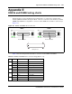
Analog telephony devices, such as single-line telephones, modems, and fax machines, are
connected to the analog station module (ASM) through the RJ-21 connector on the front of the
media bay module (MBM) (see Figure 194).
Figure 194 ASM RJ-21 connector
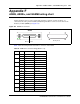
Table 92 lists the wiring details for the RJ-21 connector on the ASM.
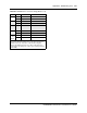
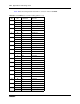
Table 92 ASM RJ-21 connector wiring (Sheet 1 of 2)
Set Pin Connection Wire color
1 26 Tip White-Blue
1 Ring Blue-White
2 27 Tip White-Orange
2 Ring Orange-White
3 28 Tip White-Green
3 Ring Green-White
429Tip White-Brown
4 Ring Brown-White
5 30 Tip White-Slate
5 Ring Slate-White
631Tip Red-Blue
6 Ring Blue-Red
7 32 Tip Red-Orange
7 Ring Orange-Red
833Tip Red-Green
8 Ring Green-Red
— 34 No connection Red-Brown
9 No connection Brown-Red
RJ-21 pin-out
RJ-21 connector
GASM8