
User's Manual


34 Chapter 2 Introducing the BCM hardware
N0060612N0060612
BCM400 main unit
The BCM400 main unit is available either in a standard or redundant feature option (RFO)
configuration.
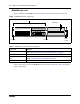
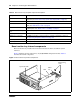
Figure 3 illustrates the BCM400 main unit, and Table 3 describes the main unit components.
These components are the same for the standard and RFO configurations.
Figure 3 BCM400 main unit components
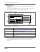
Figure 4 shows the BCM400 main unit standard configuration internal components, while Figure 5
shows the BCM400 main unit RFO internal components. Table 4 describes the internal
components.
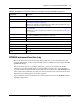
Table 3 BCM400 main unit component descriptions
Component Description
Base function tray The sliding base function tray provides call processing functions and interface
connections. See “Base function tray component hardware” on page 39.
Advanced function tray The sliding advanced function tray contains a hard disk and a bay for future use. See
“BCM400 advanced function tray” on page 37.
Tray latch The tray latch enables you to remove the base function tray or the advanced function
tray.
Media bay module (MBM)
bay
The MBM bay is a slot into which you install an MBM. See “Media bay modules
(MBMs)” on page 51.
MBM ejector The MBM ejector enables you to remove an MBM from the MBM bay.
MBM bays
Tray latch
Tray latch
Base function tray
Advanced function tray
MBM ejector
Primary Mirror
Status
Alarm Reset