
User's Manual


Appendix C GATM wiring chart 339
BCM200/400 4.0 Installation and Maintenance Guide
Appendix C
GATM wiring chart
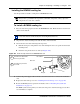
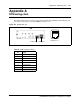
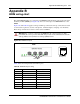
Analog telephone lines are connected to the GATM4 or GATM8 through the RJ-21 connector on
the front of the media bay module (MBM) (see Figure 191).
Figure 191 GATM RJ-21 connector
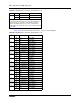
Table 87 lists the wiring details for the RJ-21 connector on the GATM4.
Table 87 GATM4 RJ-21 connector wiring (Sheet 1 of 2)
Line Pin Connection Wire color
126Tip White-Blue
1 Ring Blue-White
2 27 Tip White-Orange
2 Ring Orange-White
— 28 No connection White-Green
3 No connection Green-White
— 29 No connection White-Brown
4 No connection Brown-White
330Tip White-Slate
5 Ring Slate-White
431Tip Red-Blue
6 Ring Blue-Red
— 32 No connection Red-Orange
7 No connection Orange-Red
.
.
.
.
.
.
.
.
.
.
.
.
— 49 No connection Violet-Brown
24 No connection Brown-Violet
RJ-21 pin-outRJ-21 connector
GATM