
User's Manual


Appendix B BRIM wiring chart 337
BCM200/400 4.0 Installation and Maintenance Guide
Appendix B
BRIM wiring chart
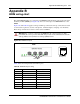
The digital BRI ISDN lines are connected to the BRIM through the RJ-45 jacks on the front of the
media bay module (MBM) (see Figure 190). You can connect up to four BRI ISDN lines to the
BRIM.
Figure 190, and Table 86 apply to S-Loop and T-Loop connections. S-Loop connections are used
to connect S-Loop devices, such as video phones, terminal adapters, and group 3 fax machines.
The T-Loop connections are used to connect to the CO/PSTN.
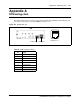
Figure 190 BRIM RJ-45 ports
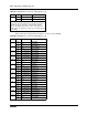
Table 86 lists the wiring details for the RJ-45 ports.
Warning: For a U-Loop connection, the BRIM must be connected only to an NT1
provided by the service provider. The NT1 must provide a Telecommunication Network
Voltage (TNV) to Safety Extra Low Voltage (SELV) barrier.
Table 86 BRIM RJ-45 port wiring
Pin Signal Signal on system side
1 No connection No connection
2 No connection No connection
3 + Receive (+Rx) +Tx
4 + Transmit (+Tx) +Rx
5 - Transmit (-Tx) -Rx
6 - Receive (-Rx) -Tx
7 No connection No connection
8 No connection No connection
1 2 3 4 5 6 7 8
RJ-45 pin-out
RJ-45 jacks
BRIM