
User's Manual


320 Chapter 24 Replacing data cards and processing hardware
N0060612N0060612
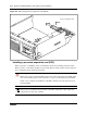
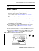
5 Partially remove the base function tray from the main unit. Do not crimp, stretch, or damage
the cables or connectors.
6 Remove the base function tray bezel. See “To remove the base function tray bezel” on page
237.
7 Remove the WAN card (if applicable). See “To remove the WAN card” on page 301.
8 Disconnect the DS30 cables from the MSC. Do not crimp, stretch, or damage the cables or
connectors.
9 Completely remove the base function tray from the main unit. See “Removing the base
function tray” on page 234.
10 Remove the media services card (see “To remove the media services card (MSC)” on page
304).
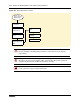
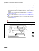
11 Use your finger to carefully lift the battery out of the socket. For the location of the battery
socket, refer to Figure 175.
Figure 175 Removing the clock/calendar battery
Caution: Do not use any type of tool to remove the battery.
Base function tray - front
CMOS
battery
The battery is located
under the edge of the
power supply