
User's Manual


Chapter 24 Replacing data cards and processing hardware 311
BCM200/400 4.0 Installation and Maintenance Guide
13 Install the MSC in the correct PCI riser card connector. See “To install the media services card
(MSC)” on page 306.
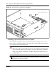
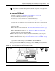
14 Install the two mounting screws that secure the MSC to the base function tray extension (at the
rear of the MSC). See Figure 164.
15 Position the WAN card (if applicable) in the top PCI riser card connector. See “Installing the
WAN card” on page 302.
16 Partially install the base function tray in the main unit.
17 Connect the DS30 connectors to the MSC.
18 Position the PCI cover plate on the front of the base function tray so that the base function tray
and cover plate screw holes align.
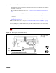
19 Position the PCI cover plate locking screw in the PCI cover plate. Tighten the PCI cover plate
locking screw until the plate is firmly set in place (see Figure 163).
20 Push the base function tray completely into the main unit (see “To install the base function
tray” on page 236). Ensure you do not pinch or damage any cables.
21 Restore the BCM system to operation. For details, refer to “Restarting the system after
maintenance” on page 232.
22 Reinitialize your system.
Replacing the processor expansion card (PEC)
This section describes how to replace the processor expansion card (PEC) in the BCM200 and
BCM400 main units. This section contains the following procedures:
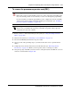
• “To remove the processor expansion card (PEC)” on page 313
• “Installing a processor expansion card (PEC)” on page 314
• “Removing the dual in-line memory module (DIMM) card” on page 316
The BCM200 is equipped with one PEC III mounted on the media services card (MSC). The
BCM400 is equipped with two PEC IIIs mounted on the MSC. The PECs provide signal
processing capabilities for such applications as voice mail and IP telephony applications.
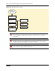
Figure 169 provides an overview of the process for replacing a PEC.