
User's Manual


310 Chapter 24 Replacing data cards and processing hardware
N0060612N0060612
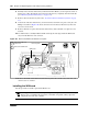
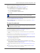
Figure 167 Modem port label
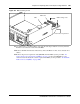
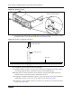
7 If applicable, install the modem card guide pin on the main card. Ensure the modem card guide
pin aligns with the correct opening on the main card (see Figure 168).
Figure 168 Modem card guide pin installation
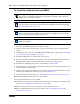
8 Carefully grasp the modem card with your fingertips.
9 Install the modem card in the correct location on the main card. Ensure the modem card pins
correctly align with the main card modem connectors and modem guide pin.
10 Gently push in a downward direction on the modem card with your fingertips. Ensure the
modem card seats correctly in the main card modem connectors.
11 If applicable, install the modem RJ-11 interface to the base function tray faceplate. Ensure the
modem RJ-11 interface connector is on the right side (as shown in Figure 166).
12 If applicable, connect the RJ-11 modem card connector to the main card socket and the RJ-11
interface (see Figure 166).
Remove modem port label
Install the modem guide pin
into the main card
Modem guide pin
Main card