
User's Manual


302 Chapter 24 Replacing data cards and processing hardware
N0060612N0060612
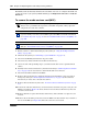
6 Partially remove the base function tray from the main unit. Ensure you do not pinch, stretch, or
damage any cables. If required, remove the base function tray completely from the main unit
(see “Removing the base function tray” on page 234).
7 Remove the base function tray bezel. See “To remove the base function tray bezel” on page
237.
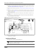
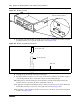
8 At the front of the base function tray, loosen and remove the PCI cover plate screw (use a #2
Phillips screwdriver). Figure 162 shows an interior view of the base function tray. Place the
screw in a safe location.
9 Remove the PCI cover plate from the base function tray. Place the PCI cover plate in a safe
location.
10 Use both hands to carefully hold the WAN card along the side edges. Push the WAN card
away from the PCI riser card connector.
Figure 162 Remove the WAN card and PCI cover plate
11 Remove the WAN card from the base function tray. Place the card in a safe, static-free, and
clean location or container.
Installing the WAN card
Use this procedure to install a replacement WAN card.
Warning: Protect the hardware components against damage from electrostatic discharge.
Always wear a grounded wrist strap before you handle components. Always place the
components in a static-free container.
PCI cover plate
WAN card
1
2
Remove the PCI cover
plate screw
Remove the WAN card
1
2