
User's Manual


300 Chapter 24 Replacing data cards and processing hardware
N0060612N0060612
• “To remove a DIMM card” on page 317
• “To install a DIMM card” on page 318
• “To remove the clock/calendar battery” on page 319
• “To install a new clock/calendar battery” on page 321
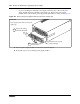
Figure 160 shows an interior view of the base function tray (looking forward). The illustration
identifies the location of interior components. Use the flowchart shown in Figure 161 to replace
the cards.
Figure 160 Base function tray interior components
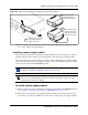
Danger: Electrical shock warning.
Disconnect the power cord, telephone cables, and network cables before opening the
computer. Read and follow installation instructions carefully.
Caution: Use only a Nortel-approved replacement. Contact your account representative
for the current list of approved replacement parts.
PCI cover screwPCI cover plate
PCI Riser
card
connectors
Main card
WAN slot MSC slot
Modem
card
Modem card
interface