
User's Manual


Chapter 23 Replacing or upgrading a power supply 293
BCM200/400 4.0 Installation and Maintenance Guide
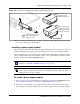
Figure 154 Install a cable grommet
20 Install the main unit top cover. See “Installing the main unit top cover” on page 246.
Removing a BCM400 redundant power supply cage
Use this procedure to remove an existing redundant power supply cage from the BCM400 main
unit.
To remove a BCM400 redundant power supply cage
1 Set up the BCM400 for maintenance (see “Performing a system shutdown” on page 231).
2 Disconnect all cables from the front of the base function tray.
3 Disconnect the main unit and the expansion unit (if applicable), from the AC power
connection.
4 Remove the top cover from the BCM400 main unit (see “Removing the main unit top cover”
on page 244).
5 Attach one end of the grounding strap to your wrist and the other end to a grounded metal
surface.
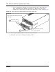
6 Remove the power supply modules (see “Removing a power supply module” on page 297).
7 Partially remove the power supply module from the power supply cage. Do not completely
remove the power supply module.
Warning: Protect the hardware components against damage from electrostatic discharge.
Always wear a grounded wrist strap before you handle components. Always place the
components in a static-free container.
Cable grommet
Insert the P2, P3
and auxiliary
cables into the
cable slot
Cable slot