
User's Manual


Chapter 23 Replacing or upgrading a power supply 289
BCM200/400 4.0 Installation and Maintenance Guide
To install a redundant power supply cage (BCM400 only)
1 Shut down the system (see “Performing a system shutdown” on page 231).
2 Disconnect the BCM400 system from the AC power outlet.
3 Remove the standard power supply from the main unit (see “Removing a BCM400 standard
power supply” on page 282).
4 Remove the power supply support bracket from the main unit (see “Removing a BCM400
standard power supply” on page 282).
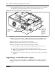
5 Remove the power supply adapter tab from the support bracket (see Figure 149). Use pliers to
bend and snap the tab away from the support bracket. Make sure you remove only the inner
adapter tab.
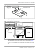
Figure 149 Remove the BCM400 power supply adapter tab from the support bracket
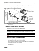
6 Remove the knockout bracket from the rear of the main unit (see Figure 150).
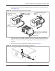
Note: When you install a redundant power supply, you must also remove the jumper
installed in the PSU Status connector (RPS output signaling connector) on the I/O card.
See “Removing the PSU status connector jumper” on page 287.
Warning: Protect the hardware components against damage from electrostatic discharge.
Always wear a grounded wrist strap before you handle components. Always place the
components in a static-free container.
Remove the inner
adapter tab