
User's Manual


Chapter 23 Replacing or upgrading a power supply 287
BCM200/400 4.0 Installation and Maintenance Guide
• “Removing the PSU status connector jumper” on page 287
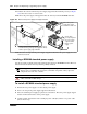
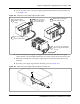
• “Installing a redundant power supply cage (BCM400 only)” on page 288
• “Removing a BCM400 redundant power supply cage” on page 293
• “Installing a power supply module” on page 295
• “Removing a power supply module” on page 297
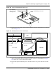
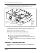
Figure 147 provides an overview of the steps required to upgrade your BCM400 system from a
standard power supply to a redundant power supply.
Figure 147 Redundant power supply upgrade overview
Removing the PSU status connector jumper
Use this procedure if you are installing a redundant power supply for the first time. Use this
procedure only with the BCM400 main unit.
Note: A BCM expansion unit with a standard power supply cannot be upgraded. You
must replace the expansion unit.
Note: When you install a redundant power supply, you must also install a redundant
cooling fan included with the redundancy upgrade kit.
Note: When you install a redundant power supply, you must also remove the jumper
installed in the power supply unit status connector (RPS output signaling connector) on
the I/O card.
Note: When you upgrade to a redundant power supply, you must also install a redundant
fan. Refer to “Installing a BCM400 cooling fan” on page 326.
Shut down the
system
Install redundant
power supply
cage
Remove PSU
jumper
Insert both
modules into
power supply
cage
Restore unit to
operation
Check power LED
Note cable
routing. Remove
cables
Remove the
standard power
supply
Make internal
connections
Set up unit for
maintenance