
User's Manual


286 Chapter 23 Replacing or upgrading a power supply
N0060612N0060612
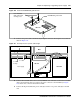
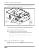
9 Align the mounting holes in the power supply with the chassis holes at the rear of the main
unit. Fasten the power supply mounting screws to the main unit (see Figure 146).
Figure 146 Fasten the standard power supply to the main unit
10 Attach the 20-pin motherboard connector and the +12V power connector into the I/O card.
11 Route the power cable, auxiliary, and IDE cables to the hard disk cage. Bundle the cables
together and fasten to the roof of the main unit using the cable clamp (see Figure 146).
12 Connect the power cable and IDE cable to the hard disk.
13 Run the auxiliary cable to the chassis cable slot (see the next step).
14 Connect cable runs P2 and P3 to the media bay backplane as follows.
a Connect cable P2 into the bottom media bay module backplane power connector.
b Connect cable P3 into the top media bay module backplane connector.
c Bundle power cables P2 and P3 along with auxiliary cable (P7 or P8) together with a
grommet (see Figure 154).
d Insert the P2, P3, and auxiliary cable into the cable slot on the chassis (secured with the
grommet).
Upgrading to a redundant power supply
Use the procedures in this section to upgrade a BCM400 main unit, currently equipped with a
standard power supply, with a redundant power supply. This section contains the following
procedures:
Fasten power,
auxiliary, IDE
cables using
cable clamp -
located on
underside of
cover
Fasten power
supply mounting
screws