
User's Manual


180 Chapter 13 Initializing the system
N0060612N0060612
Null modem cable setup
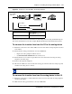
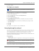
Table 63 and Figure 91 show the correct wiring for the BCM serial port of the null modem cable.
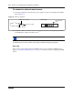
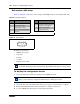
Figure 91 Serial pinout
Transmission parameters:
• 9600 bits per second
• 8 data bits
•no parity
• 1 stop bit
• hardware flow control
To display the configuration menus
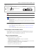
1 Attach the null modem cable to the serial port on the BCM main unit.
2 Attach the other end of the null modem cable to the serial port on the terminal or computer.
3 Ensure that the BCM main unit and your terminal or computer are turned on.
4 Access the BCM main unit using one of the following methods:
Table 63 Serial port pinout
Pin Signal Pin Signal
1 Data Carrier Detect (DCD) 6 Data Set Ready (DSR)
2 * Serial data in (RX) 7 Request to Send (RTS)
3 * Serial data out (TX) 8 Clear to Send (CTS)
4 Data Terminal Ready (DTR) 9 Ring Indicator (RI)
5 * Ground
* required connections
Note: For instructions about how to set the transmission parameters, refer to the terminal
or terminal emulation program documentation. The BCM system supports carriage return.
Note: The location of the transmit (TX) and receive (RX) pins on your terminal can vary.
Refer to your terminal or computer documentation to confirm pin locations.
12345
6789