
User's Manual


Chapter 9 Connecting the cables 157
BCM200/400 4.0 Installation and Maintenance Guide
To connect the BCM system to the WAN
1 Ensure the system is powered up before connecting this cable.
2 Do one of the following:
• To connect the WAN card using the RJ-48C connector, insert the wide area network
(WAN) cable into the RJ-48C jack on the WAN card (see Figure 79 on page 156).
• To connect the WAN card using the DB26 connector, use an adapter cable to connect the
wide area network (WAN) cable to the DB26 connector on the WAN card. These adapter
cables are available from your BCM supplier (see Figure 79 on page 156).
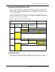
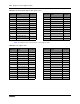
Table 57 shows the wire connections for a DB26 adapter cable.
To connect the modem
1 Ensure the system is powered up before connecting this cable.
2 Insert a PSTN line into the line jack on the modem interface (see Figure 79 on page 156).
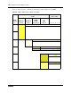
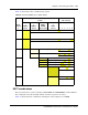
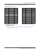
Table 58 shows the wire connections for a RS-422/EIA 530 cable.
Table 57 DB26 adapter cable
DB26 on
WAN card Signal DB26 cable
DB26 on
WAN card Signal DB26 cable
1 Chassis Ground 1 14 14
2 Transmit Data 2 15 Transmit Clock 15
3 Receive Data 3 16 16
4 Request to Send 4 17 Receive Clock 17
5 Clear to Send 5 18 18
6 Data Set Ready 6 19 19
7 Signal Ground/
Common Return
7 20 Data Terminal Ready 20
8 Data Carrier Detect 8 21 21
9 9 22 22
10 10 23 23
11 11 24 External Clock 24
12 12 25 25
13 13 26
Table 58 RS-422/EIA 530 adapter cable (Sheet 1 of 2)
DB26 on
WAN card
Signal
RS-422/EIA
530 cable
DB26 on
WAN card
Signal
RS-422/EIA
530 cable
1 Protective Ground 1 14 Transmit Data B 14
2 Transmit Data A 2 15 Transmit Clock A 15