
User's Manual


Chapter 9 Connecting the cables 155
BCM200/400 4.0 Installation and Maintenance Guide
• The goal is to have a balanced mix of trunk and station MBMs.
• Write the DIP switch settings for each module in a place that is handy to reference when you
decide to change or add MBMs.
• If you update your Norstar system to a BCM system, your station amphenol connectors can be
connected into the MBMs without adjustment. Trunk connectors must be converted to RJ-11
(CTM) or RJ-45 (BRI) connectors. However, if you use the FEM to connect your Norstar
MBMs to the BCM system, the station wiring must be adjusted. Refer to “Wiring the FEM” on
page 148.
System setup
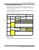
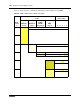
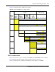
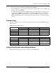
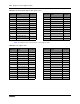
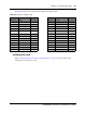
Use Table 56 to make a note of your basic system setup. Post this page near the BCM hardware for
future reference.
Connecting the data networking hardware
This section describes how to connect network cards to the BCM system.
Table 56 System setup summary
DS30 bus 2 DS30 bus 3 DS30 bus 4
Media bay module
Dip switch setting
Line/set type
Line/Loop/DN range
DS30 bus 5 DS30 bus 6 DS30 bus 7
Media bay module
Dip switch setting
Line/set type
Line/Loop/DN range