
User's Manual


Chapter 9 Connecting the cables 149
BCM200/400 4.0 Installation and Maintenance Guide
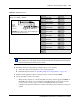
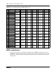
Table 50 compares the designated extension numbers on the Norstar and on the BCM systems.
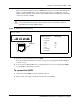
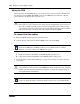
Setting DNs and port numbers
The MBM, based on the switch settings, defines which DNs and port numbers can be populated
with telephones. If you have changed the default start DN for your system, use Table 51 to identify
the DNs and ports for your sets. If you are using the default start DN (221), a completed chart is
provided in Table 61 on page 163.
Table 50 Extension comparison chart
Ports 1 2 3 4 5 6 7 8 9 10 11 12 13 14 15 16
DS30 bus 2, FEM port 1
Norstar 221 222 223 224 225 226 227 228 229 230 231 232 233 234 235 236
BCM 225 226 227 228 221 222 223 224 233 234 235 236 229 230 231 232
DS30 bus 3, FEM port 2
Norstar 237 238 239 240 241 242 243 244 245 246 247 248 249 250 251 252
BCM 241 242 243 244 237 238 239 240 249 250 251 252 245 246 247 248
DS30 bus 4, FEM port 3
Norstar 253 254 255 256 257 258 259 260 261 262 263 264 265 266 267 268
BCM 257 258 259 260 253 254 255 256 265 266 267 268 261 262 263 264
DS30 bus 5, FEM port 4
Norstar 269 270 271 272 273 274 275 276 277 278 279 280 281 282 283 284
BCM 273 274 275 276 269 270 271 272 281 282 283 284 277 278 279 280
DS30 bus 6, FEM port 5
Norstar 285 286 287 288 289 290 291 292 293 294 295 296 297 298 299 300
BCM 289 290 291 292 285 286 287 288 297 298 299 300 293 294 295 296
DS30 bus 7, FEM port 6
Norstar 301 302 303 304 305 306 307 308 309 310 311 312 313 314 315 316
BCM 305 306 307 308 301 302 303 304 313 314 315 316 309 310 311 312
Table 51 Cross-referencing ports and DNs (Sheet 1 of 2)
Pin Wire color
DS30 bus
2
DS30 bus
3
DS30 bus
4
DS30 bus
5
DS30 bus
6
DS30 bus
7
26 White-Blue DN
Port 201
DN
Port 301
DN
Port 401
DN
Port 501
DN
Port 601
DN
Port 701
1 Blue-White
27 White-Orange DN
Port 202
DN
Port 302
DN
Port 402
DN
Port 502
DN
Port 602
DN
Port 702
2 Orange-White
28 White-Green DN
Port 203
DN
Port 303
DN
Port 403
DN
Port 503
DN
Port 603
DN
Port 703
3 Green-White