
User's Manual


Chapter 9 Connecting the cables 147
BCM200/400 4.0 Installation and Maintenance Guide
2 Install the telephones and peripheral equipment (if it is a new system):
a Attach the cables for the telephones to the connecting blocks.
b Install the telephones. Refer to “Installing telephones and peripherals” on page 161.
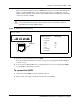
3 Plug the female amphenol connector into the interface on the front of the MBM.
4 Set up any mobile system you are using.
• Ensure the base stations are correctly installed and connected to the appropriate MBMs on
the BCM system. In the case of the Wireless LAN IP telephone system, ensure that the
access point is correctly set up to connect to the BCM system LAN or WAN.
• Configure and register the handsets according to the instructions provided for each type of
system.
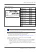
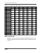
Table 49 ASM wiring chart
Pin Wire color Port Set #
Wiring for an ASM 8 or GASM8
26 White-Blue X01 1
1 Blue-White X01 1
27 White-Orange X02 2
2 Orange-White X02 2
28 White-Green X03 3
3 Green-White X03 3
29 White-Brown X04 4
4 Brown-White X04 4
30 White-Slate X05 5
5 Slate-White X05 5
31 Red-Blue X06 6
6 Blue-Red X06 6
32 Red-Orange X07 7
7 Orange-Red X07 7
33 Red-Green X08 8
8 Green-Red X08 8
34-50 no connection
9-25
Note: Refer to “Assigning line and extension numbers” on page 121 to see the
relationship between the DS30 channel number and the DNs. Configuration information is
included in the BCM 4.0 Administration Guide.
25-pair
female
amphenol
connector
8T
33R
32R
7T
31R
6T
30R
5T
29R
4T
28R
3T
27R
2T
26R
1T
WARNING: Ensure that you have Tip (T) and Ring (R)
connected to the appropriate pins.