
User's Manual


140 Chapter 9 Connecting the cables
N0060612N0060612
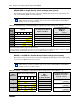
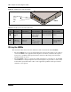
Figure 74 Module power and status LEDs
Wiring the MBMs
This section describes how to wire the cables that connect to the station and trunk MBMs.
• The station MBMs have one or two 50-pin amphenol connectors that require 25-pair cables to
connect the MBMs to the equipment in the telephone room where your demarcation point is
located. Use a qualified technical professional to ensure the cable wiring and your interior
telephone wiring are correct.
• The trunk MBMs connect to central office trunks using RJ-type jacks. However, the GATM4
and GATM8 have a 50-pin amphenol connector that requires a 25-pair cable to connect to the
Central Office (CO) trunk. These cables can be supplied by qualified technical personnel to
ensure the correct pin-out.
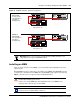
Table 47 Module power and status LED states
LED
Label Description Green LED On Green LED Flash Red LED On (Only) Green LED Off
Indicates state
of system
power
OK Check for hardware
problem with fan,
power, or heat
inside housing
A minimum of 1 power
supply needs attention
No power to the
module
Indicates
condition of
system status
All monitored
services are
functioning
In startup/shutdown
mode
check for problem
with MSC wiring
N/A Not all services are
working, MSC may
not have started
correctly
All modules have a
power
and
status
LED
DSM16