
User's Manual


Chapter 9 Connecting the cables 139
BCM200/400 4.0 Installation and Maintenance Guide
Checking system power and status
After you connect power to the BCM system, the power LED on the front of the base function tray
and expansion unit lights. Once the system services have reactivated, the status LED turns solid
green. For further information on LED indicators, see “Viewing the BCM system LEDs” on page
77.
The power LED can indicate RED if the system is in standby mode whereby power is available but
shut down by the operating system or Overtemp.
LEDs in position 3 to 8 will flash when the SSM is not communicating (during startup, shutdown,
or operating system hang).
To check system power and status
1 If the base function tray power LED does not light:
a Disconnect the power cords.
b Check all cables and power connections. Ensure that the AC outlet has power.
c Reconnect the power cords.
2 If the power LED is red and there is no power, use a paper clip to select the reset button.
Alternatively, power cycle the system to restart.
3 You are now ready to connect the system to the network and initialize it.
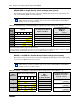
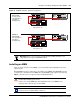
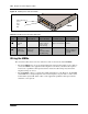
When the system power is on, and the system has successfully booted, the power and status LEDs
on the faceplates of the MBM are lit and remain constant. Figure 74 shows an example of an MBM
and the LEDs on the MBM faceplate. Table 47 provides a description of the MBM power and
status LED states.
Note: During system initialization, the system performs diagnostics on the hardware
configuration size and installation. If the power fails, system data remains in memory.
Note: You can monitor the state of the BCM system LEDs from your computer.