
User's Manual


Chapter 8 Installing a media bay module (MBM) 133
BCM200/400 4.0 Installation and Maintenance Guide
FEM switch settings
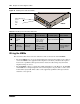
The DIP switches on the underside of the FEM are used to turn the six ports on the front of the
module on or off. You need to turn a port on for each Norstar expansion module you want to
connect to the BCM system. Each port also occupies one full DS30 bus. Therefore, if you have a
fully configured, six-module Norstar system to convert, you must turn on all six ports on the FEM,
and, therefore, no other module can be installed in the BCM system.
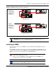
To turn on a fiber port, set the DIP switch for the corresponding DS30 bus, as shown in Table 46.
For example, if you want to use fiber port 2, turn on DIP switch 2 (DS30 3). After the module is
installed, an LED lights beside each active fiber port.
Table 46 shows the switch for each fiber port.
5
off on on on off off A
317-332 A 333-348
off on off on off off B
333-348 B 317-332
6
off on on off on on A
349-364 A 365-380
off on off off on on B
365-380 B 349-364
**7
off on on off on off A
381-396 A 397-412
off on off off on off B
397-412 B 381-396
* The extensions listed are based on a three-digit DN with a Start DN of 221. If your system has longer DNs or a
different Start DN, enter the range in the blank column.
** If your system is configured with a 3/5 split, you cannot use DS30 7.
Note: The FEM module only supports connections to the Norstar trunk and station
expansion modules.
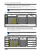
Table 46 FEM switch settings
Choose a port
to turn on
Set this switch to turn on the port
This DS30 bus is
assigned
123456
1 ON 2
2 ON 3
3 ON 4
4 ON 5
5 ON 6
6 ON 7*
* If your system is configured with a 3/5 split, DS30 7 is not available.
Note: If you turn on all six switches, you are using all the DS30 numbers. In this case, the
BCM system can support only the FEM module. All other media bays must be empty.
Table 45 DSM 16+ and DSM32+ double density switch settings (new system) (Sheet 2 of 2)