
User's Manual


Chapter 8 Installing a media bay module (MBM) 127
BCM200/400 4.0 Installation and Maintenance Guide
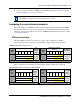
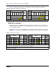
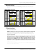
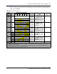
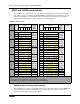
Table 38 shows the switch settings for each DS30 bus, and the assigned lines and dialing numbers
(DNs) for each DS30 bus.
Table 38 4x16 switch settings
Select
DS30
bus #
Select
offset
Enter these switch settings
To assign
these lines
And this DS30 bus
and DNs
2
Custom DN
range
123456
02 0 on on on on on
on
211-214
DS30, bus 03
237-252
(2.5 upgrade)
253-268 (new system)
1 on on offononon219-222
2 on offonononon227-230
3 on off offononon235-238
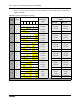
03 0 on on on on on off 181-184
DS30, bus 04
253-268
(2.5 upgrade)
285-292 (new system)
1 on on off on on off 189-192
2 on offonononoff 197-200
3 on off off on on off 205-208
04 0 on on on on off on 151-154
DS30, bus 05
269-284
(2.5 upgrade)
317-332 (new system)
1 on on off on off on 159-162
2 on off on on off on 167-170
3 on off off on off on 175-178
05 0 on on on on off off 121-124
DS30, bus 06
285-300
(2.5 upgrade)
349-364 (new system)
1 on on off on off off 129-132
2 on off on on off off 137-140
3 on off off on off off 145-148
06 0 on on on off on on 91-94
DS30, bus 07
1
301-316 (2.5 upgrade)
381-396 (new system)
1 on on off off on on 99-102
2 on off on off on on 107-110
3 on off off off on on 115-118
07
1
Not supported
1
If your system is configured with a 3/5 DS30 split, you cannot configure this module for DS30 6 because DS30 7 is
not available for the second level.
2
The extensions listed are based on a three-digit DN with a Start DN of 221. If your system has longer DNs or a
different Start DN, enter the range in the blank column.