
User's Manual


116 Chapter 8 Installing a media bay module (MBM)
N0060612N0060612
Determining MBM DIP switch settings
Assign DIP switch settings before you install an MBM. The DIP switches are located on the back
or underside of the MBM.
To determine MBM DIP switch settings
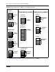
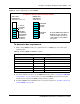
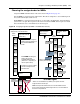
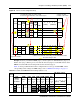
1 Use Table 28 (trunk MBMs) and Table 29 (station MBMs) to determine a switch setting for all
MBMs except the FEM. Figure 69 on page 117 shows an example of the table and how to do
the following steps.
2 On Table 28 or Table 29 circle the MBM names.
3 Number the order in which you want to assign the MBMs.
4 Determine the number of DS30s each MBM requires. For some station MBMs this depends on
whether you choose to set the MBM to single or double density.
5 Circle the DS30 bus and offset numbers.
6 Follow the DS30 bus and offset numbers to the far right column where the switch settings are
indicated. Circle the setting for each MBM.
Note: Fiber expansion module (FEM) switches
The switches on the fiber expansion module (FEM) do not work in the same way as those
of the trunk or station MBMs. On the FEM, the switches turn the fiber ports on and off.
For information about setting the switches on an FEM, refer to “FEM switch settings” on
page 133.
Note: If you must assign specific line or extension numbers to an MBM, refer to the
individual switch tables in “Assigning line and extension numbers” on page 121 for line
and DN listings.