
User's Manual


Chapter 8 Installing a media bay module (MBM) 115
BCM200/400 4.0 Installation and Maintenance Guide
Choosing the assigned order for MBMs
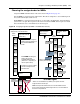
Assign the MBMs and DS30 buses in the order shown in Figure 68 on page 115.
Station MBMs are assigned starting with DS30 2. This allows telephones to start numbering from
the system Start DN (the default is 221).
Trunk MBMs are assigned starting at DS30 7 in a system with a 2/6 DS30 split, and at DS30 6 in a
system with a 3/5 split. The exception to this is the 4x16 and the DDIM, which require two DS30
buses that must be set to a DS30 that has the next bus open.
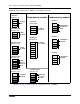
Figure 68 Assigning single-density MBMs to the DS30 bus hierarchy
Trunk MBMs are assigned
starting with the last
available MBM DS30 bus
(DS30 6 or 7, depending on
the bus split in effect).
Exception: a 4x16 or a DDIM
cannot be assigned to the
last DS30 bus.
2
3
4
5
6
7*
DS30
buses
DN assignment
begins with Start DN
(default: 221)
Station MBMs are assigned
starting at the top (DS30 2) of
the available MBM DS30
buses.
Lines start at 61 on
DS30 7
3/5 bus split
* DS30 7 is not available to any MBM if your system has been
configured with a 3/5 bus split
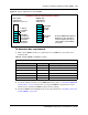
MBMs that require two DS30 buses, such as the DSM32 and the
4x16, must be assigned to DS30s higher than 6, to accommodate all
the resource requirements.
2
3
4
5
6
7*
DS30
buses
CTM
4x16
DSM 32
Example of
North American-
based setup
After you choose your MBMs, choose where to
assign them on the DS30 buses
Example of a
European- based
setup
DSM 32
DSM 16
DS30 5 supports the
station part of the 4x16
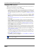
BRI
6
7*
DSM 32
DSM 32
BRI
DECT
DSM 16
CTM
CTM