
User's Manual


Chapter 8 Installing a media bay module (MBM) 113
BCM200/400 4.0 Installation and Maintenance Guide
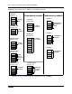
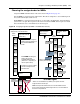
Figure 67 Space requirements for special MBMs
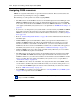
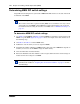
To determine bus requirements
1 Make a list of MBMs and the space requirements for each MBM you chose. Refer to the
following table.
2 Set the bus numbers and offsets on the MBM DIP switches. Refer to “Determining MBM DIP
switch settings” on page 116. Note that you assign trunk MBMs starting from the bottom
DS30, and you assign station MBMs starting from the top DS30.
3 Install the MBMs into the BCM main unit or expansion unit. Refer to “Installing a media bay
module (MBM)” on page 105.
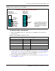
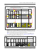
Table 27 Matching MBMs to DS30 bus capacity
DS30 split 2/6 (default) _____ 3/5 (extra IP lines) _____
Type of module Number required DS30s/offsets required
Combination and specialized media bay modules
Note: The FEM module requires a
DS30 bus for each port that is
active. If all ports are active, no
other modules can be added to
the system.
4x16 module
2 DS30 buses/
offset set to 0, 1, 2, or 3
DDIM module
2 DS30 buses/
offset set to 0
1 offset of
1 full DS30
for lines
1 full DS30
for telephone
and equipment
connections
1/2 DS30 for
the stations
1 full DS30
for DTM
module
1 full DS30
for data