
User's Manual


Chapter 7 Installing an expansion unit 103
BCM200/400 4.0 Installation and Maintenance Guide
Connecting the BCM expansion unit to the BCM main unit
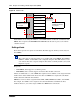
After the expansion unit is installed in the desired location, use the supplied DS256 cable
(NTAB3086) to connect it to the BCM main unit. The cable has the following characteristics:
• all 8 pins must be connected as shown in Table 24 and Figure 60.
• the cable must be shielded
• the cable must be exactly 5 m long
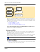
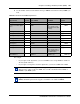
Figure 60 DS256 cable
Table 24 DS256 cable pinout
Signal name
Expansion unit
PIN
Main unit
PIN Circuit name Color
TXD + 1 1 PAIR 3 (-) White-Green
TXD - 2 2 PAIR 3 (+) Green
SYNC + 3 3 PAIR 2 (-) White-Orange
CLK + 4 4 PAIR 1 (+) Blue
CLK - 5 5 PAIR 1 (-) White-Blue
SYNC - 6 6 PAIR 2 (+) Orange
RXD + 7 7 PAIR 4 (-) White-Brown
RXD - 8 8 PAIR 4 (+) Brown
Warning: The timing in the BCM system is critical. Use the correct length cable as
supplied with the expansion unit. The system will not work properly if you connect the
BCM expansion unit using a cable that varies in length.
Pin 1
Pin 1