Contents Overview................................................................................................................................5 NB5Plus4/W Package Contents.......................................................................................6 Minimum System Requirements.......................................................................................7 Do I need a Micro filter? . ................................................................................................
QoS Setup Page.......................................................................................................45 Rules Configuration Page.........................................................................................46 Traffic Queuing Configuration...................................................................................47 Queue Priorities:..................................................................................................47 Configuration:.............................
Wireless Main Screen.....................................................................................................80 Wireless>Setup.........................................................................................................81 Wireless Setup Field Descriptions.......................................................................81 User Isolation .....................................................................................................83 Save Your Changes.......................
Overview Thank you for purchasing the NetComm NB5Plus4/W ADSL/ADSL2 Modem Router. NetComm brings you the Next Generation of ADSL technology with ADSL-2*, which boosts ADSL’s performance, improves interoperability, and supports new applications, services and deployment conditions. NetComm’s implementation of ADSL-2* and ADSL-2+* ensures that the NB5Plus4/ W operates with existing ADSL services while delivering optimal performance in all modes of operation.
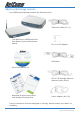
NB5Plus4/W Package Contents Your NB5Plus4/W Package contains the following items: • • • The NB5Plus4 or NB5Plus4/W Modem Router (both models shown above) • Telephone Cable (RJ-11) • RJ-11 to 605 Adaptor • USB Cable • CAT-5 UTP Straight Ethernet Network Cable (RJ-45) • Power Adaptor (AC 15V) Driver and Manual CD NB5Plus4/W Quick Start Guide and Package Contents Note If any of the above items are damaged or missing, please contact your dealer immediately.
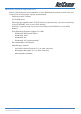
Minimum System Requirements Before continuing with the installation of your NB5Plus4/W, please confirm that you comply with the minimum system requirements.
Do I need a Micro filter? Micro filters are used to prevent common telephone equipment, such as phones, answering machines and fax machines, from interfering with your ADSL service. If your ADSL enabled phone line is being used with any other equipment other than your ADSL Modem then you will need to use one Micro filter for each phone device. Splitters may be installed when your ADSL line is installed or when your current phone line is upgraded to ADSL.
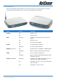
LED Indicators The LED Indicators are located on the front of the unit, they are green in colour, except the Power LED which is red. The meanings are as follows: Label Status Indicates Power On Power is on. Off Power is off. PPP Flashing Trying to authenticate with ISP’s PPP server. On PPP link is up. Off No PPP link available. On A valid ADSL connection. Flashing An active WAN session. On Wireless link is enabled on NB5Plus4W. Flashing Data is being transmitted wirelessly.
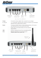
Back Panel Ports Power jack for AC power adaptor 4 x RJ-45 Ports for 10/100 Ethernet LAN Reset factory defaults USB Port RJ11 for ADSL connection to telephone line Rear Panel of the NB5Plus4 Power Connect the Power Adapt0r that comes with your package. 1, 2, 3, 4 4 x 10/100 Base-T Ethernet jack (RJ-45) to connect to your Ethernet Network card or Ethernet Hub / Switch. Reset To reset your ADSL Router to factory default settings.
Restoring Factory Defaults This feature will reset the Modem to its factory default configuration. Occasions may present themselves where you need to restore the factory defaults on your modem. Typical situations are: • You have lost your username and password and are unable to login to the modem. • You have purchased the modem from someone else and need to reconfigure the device to work with your ISP. • You are asked to perform a factory reset by a member of the NetComm Support staff.
Default Settings LAN (Management) Field Setting Details Static IP Address: 192.168.1.1 * Subnet Mask: 255.255.255.0 * Default Gateway: blank WAN (Internet) Field Setting Details User Name: username@isp Password: **** Protocol: PPPoE VPI: 8* VCI: 35 * IP Address: 192.168.1.1 * Subnet Mask: 255.255.255.0 * Default Gateway: 0.0.0.0 * Modem Access Field Setting Details User Name: admin Password: admin * Default Setting.
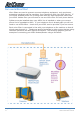
Connecting your NB5Plus4/W The NB5Plus4/W can be connected via a USB cable or an Ethernet cable or both. The USB connection is simply an ethernet simulation. As far as your computer is concerned the USB connection is an Ethernet connection, hence DHCP and other protocols will work the same as for Ethernet. To connect to your ADSL Router, you need to have either an Ethernet Port or a USB Port present on your Computer/Notebook. Connecting your NB5Plus4/W ADSL Modem via ETHERNET 1.
Connecting your NB5Plus4/W ADSL Modem via USB 1. Connect the power pack to the NB5Plus4/W ADSL Modem and switch on the power switch. 2. Connect your NB5Plus4/W to a computer directly via USB cable. 3. When the computer is booted, the Add New Hardware Wizard will launch and prompt you to provide a driver for your NB5Plus4/W ADSL Modem. Insert the CD provided. 4. Follow the on-screen prompts to load the driver. Refer to the section below for more detailed information.
NB5Plus4W Antenna Instructions Before continuing with the Hardware installation, you may need to connect the Antenna 1. The antenna has a retaining nut which must be screwed into the SMA connector on the back of the modem. Place the screw retaining nut over the antenna connection on the rear of the NB5Plus4W and turn it clockwise. Note: Do not over-tighten the attaching nut - but do make sure that you have screwed it all the way to its end.
Configuring your NB5Plus4/W You will need to log directly into the configuration page of the modem and configure the basic settings for your Internet connection. Your ISP should provide you with the necessary information to complete this step. The settings that you most likely need to change to access the Internet are grouped onto a single EasyConfig page. To configure your modem follow the steps below: Note: Ensure that your PC is setup as a DHCP client.
4. Check with your ISP what Protocol your modem needs to use to connect to the Internet. If unsure, leave the default selection of PPPoE. 5. In the User ID field, enter the Username that your ISP has provided. In the password field, enter the password that your ISP has given you. Note: If your ISP has provided you with Static addressing details you will need to access the Advanced Settings of your modem to configure these. Please refer to the section on Advanced Settings in this manual for instructions.
Computer Hardware Configuration This section provides instructions for configuring the TCP/IP (Network) settings on your computer to work with your Modem. These steps are only required if you are having trouble accessing your Modem. Windows® XP PCs 1. 2. 3. 4. In the Windows task bar, click the Start button, and then click Control Panel. Click on Network & Internet Connections icon. (Category mode only). Click the Network Connections icon.
7. Select Microsoft in the Manufacturers box. 8. Select Internet Protocol (TCP/IP) in the Network Protocols list, and then click OK. You may be prompted to install files from your Windows ME installation CD or other media. Follow the instructions to install the files. If prompted, click OK to restart your computer with the new settings. Next, configure the PC to accept IP information assigned by the modem: 9. Follow steps 1 – 4 above.. 10.
Advanced Settings To access the Advanced Settings of your modem you click on the Advanced Settings link on the EasyConfig web page. To access this page, enter http://192.168.1.1 and login with username ‘admin’ and password ‘admin’. NB5Plus4/W User Guide 20 YML754Rev1 www.netcomm.com.
Setup Click the Setup tab. The Setup screen allows you to change current settings for your LAN (Local Area Network), Ethernet Switch and WAN (Wide Area Network). You can also create new connection profiles. YML754 Rev1 NB5Plus4/W User Guide www.netcomm.com.
Setup>LAN Configuration Click on the LAN Configuration link under the Setup menu to configure your Local Area Network settings. Interfaces This section displays the available interfaces on your modem that have yet to be configured. The default setting is to have all interfaces in LAN group 1.
LanGroup #3 IP Address 192.168.3.1 NetMask 255.255.255.0 The above example shows that each LAN group is on its own network and that there is no overlap in assignable IP address based on netmask. To remove an interface from LAN group 1, click on the interface (e.g. USB) and click the Remove button: To add the available interface from the Interfaces section to a LAN group, highlight the interface and click the Add button of the appropriate LAN group.
Configuring LAN Groups To configure an interface of a LAN group click the interface and click the Configure hyperlink. E.g. to configure the Ethernet interface for LAN group 1 click the Ethernet interface and click the Configure hyperlink: You will be presented with the following screen: NB5Plus4/W User Guide 24 YML754Rev1 www.netcomm.com.
IP Settings The IP address is usually 192.168.1.1 but you can change it to another suitable number (e.g. 192.168.0.1 or 10.0.0.1 or 172.16.1.1) to suit any existing network devices you already have installed. The NetMask describes how big your network is, the default 255.255.255.0 will allow for 253 computers and generally does not need to be changed unless to suit existing network requirements.
Option Description Renew button It is possible to renew the IP address by clicking the Release button. PPP IP Address The IP address to be used during a PPP session. This defaults to the IP address of the interface. Use the following static IP address (Default) This is the IP address of your Modem on your local network. This IP address is specified on all computers on your network as the Gateway IP address.
Services It is possible to set the services for an interface by clicking on the hyperlink which will take you to the page to configure them. Please refer to the relevant section in this manual for information on the settings for these services. Ethernet Switch The 4-port Ethernet switch of your modem is set to automatically adapt to the type of connection plugged into a specific port. To force a port to connect at a specific speed, select the setting from the dropdown menu of a port.
WAN Setup>New Connection If you click ‘New Connection’ you will see the screen shown below. The Connection setup page requires you to choose the correct settings to work with your ADSL connection as specified by your ISP. The screen will add or remove nonapplicable choices as you change options. There are a few main settings you will need to confirm with your ISP before you can complete this page, these are; • Type of Connection (e.g.
Option Description Options: NAT (Network Address Translation allows you to share the public IP address assigned to the WAN (Wide Area Network) interface of your modem with multiple clients on your LAN (Local Area Network). NAT also acts as a basic firewall. The firewall feature protects the PCs on your LAN from malicious attacks from people on the Internet (e.g. DOS attacks).
PPPoE Connection Setup PPP Settings Option Description Username: Enter the username provided by your ISP. Password: Enter the password provided by your ISP. Idle Timeout: Idle timeout means the router will disconnect after being idle for a preset amount of time. The default is 60 seconds. If you set the time to 0, the ADSL connection will remain always connected to the ISP. Keep Alive: If mode is LCP, This is the Keep Alive timer.
Option Description On Demand: If enabled the Idle Timeout field can be modified. On Demand specifies that the modem will connect to the Internet on demand. Default Gateway: Specifies that this connection will be the default gateway for other LAN groups to access the Internet. Enforce MTU: Specifies that the MTU setting will be enforced. Debug: Enable to turn on the debugging mode of your modem.
PVC (Private Virtual Circuit) Settings Option Description VPI: (Virtual Path Identifier) If instructed to change this, type in the VPI value for the initial connection (using PVC 0). Default = 0. VCI: (Virtual Channel Identifier) If instructed to change this, type in the VCI value for the initial connection (using PVC 0). Default = 0. Your modem can support up to 8 PVCs. For example, you could have one PVC (8/35) for your Internet traffic, and another PVC (9/35) for your VoIP traffic.
PPPoA Connection Setup When specifying your connection Type to be PPPoA you are able to change the Encapsulation to either LLC (Logical Link Control) or VC (Virtual Circuit) encapsulation. The default is LLC so do not change this setting unless your ISP instructs you to do so. YML754 Rev1 NB5Plus4/W User Guide www.netcomm.com.
Static Connection Setup Option Description Encapsulation: Select the method of encapsulation used by your ISP. The default is LLC, so only change this to VC if your ISP asks you to. IP Address: If your ISP has issued you with a static public IP address, you need to specify it here. (e.g. 210.1.123.123). Mask: The subnet mask specified by your ISP. Default Gateway: The default gateway specified by your ISP.
DHCP Connection Setup Option Description Encapsulation: Select the method of encapsulation used by your ISP from the drop-down list box. Choices vary depending on the mode you select in the Mode field. IP Address: The IP address assigned by an external DHCP server. Mask: The subnet mask assigned by an external DHCP server. Gateway: The gateway assigned by your DHCP server.
CLIP Connection Setup Option Description IP Address: The public IP address assigned by your ISP for the Classical IP over ATM connection. Mask: The subnet mask issued by your ISP for the CLIP connection. ARP Server: The ARP (Address Resolution Protocol) server used by your modem. Default Gateway: Specify the default gateway used by your modem (issued by your ISP). NB5Plus4/W User Guide 36 YML754Rev1 www.netcomm.com.
WAN Setup>Modem Here you can choose one of four ADSL handshake types, typically MMode (Multimode) will work on Australian ADSL lines. You should not need to change this setting unless advised by your ISP. Option Description T1413: Full-Rate (ANSI T1.413 Issue 2) with line rate support of up to 8 Mbps downstream and 832 Kbps upstream. GDMT: Full-Rate (G.dmt, G992.1) with line rate support of up to 8 Mbps downstream and 832 Kbps upstream. GLITE: G.lite (G.992.
Logout Click Log Out to logout of the modem’s configuration interface. NB5Plus4/W User Guide 38 YML754Rev1 www.netcomm.com.
Advanced The Advanced menu allows you to configure a number of features of your modem. This section deals with these features. YML754 Rev1 NB5Plus4/W User Guide www.netcomm.com.
Advanced>UPnP Your modem is Universal Plug ‘n Play Capable, for security this feature is disabled by default. UPnP is a method of allowing devices and computer software on your Network to be able to configure ‘unblocked’ ports through your modem (and through your modem’s firewall). This makes it easier to run Network games and Programs like Microsoft Messenger etc. To Enable UPnP click the Enable UPnP box and choose the WAN connection (usually ‘PPPoE’). Select the LAN Connection (e.g.
Advanced>SNTP SNTP (Simple Network Time Protocol) allows your modem to update its time automatically using an SNTP server. To enable this feature, click the Enable SNTP tick box. YML754 Rev1 www.netcomm.com.
Option Primary, Secondary, Tertiary SNTP Servers Description This allows you to enter three different SNTP server addresses. If one of these servers is unavailable your modem will use an alternative. An example of an NTP server on the Internet is 128.250.36.3. Timeout: The number of seconds your modem will attempt to connect to an SNTP server before trying an alternative server should the server you are trying to connect to be unavailable.
Advanced>IPQoS IP QoS (Quality of Service) allows you to set priorities for traffic travelling through your modem. For example, you may want to prioritize your UDP traffic over your TCP traffic. Typical UDP traffic would be your VoIP (Voice over Internet Protocol) traffic. This section describes how to make use of your modem’s IPQoS feature. The NB5Plus4/W should have two primary sections for setting up IP QoS services: 1.
Rule definitions will be defined by the user by allowing the user to select matching based on Source IP, Destination IP, IP Protocol, Source Port, Destination Port, and Incoming Mac Port (switched LAN Port). These selections will define a rule and be associated with a particular queue priority: High, Medium, and Low.
One Expedited Forwarding (EF) Queue: High Priority queue with non-preemptible service. The EF queue is always scheduled first prior to the medium and low priority queues and runs to completion Two Queues (Medium and Low Priority) with Weighted Round Robin service. Based on the associated weights, packets on these queues share the remaining link bandwidth (after the EF service). The low priority queue corresponds to Best Effort service.
The Medium and Low priority queue lengths will be proportionally calculated via the queue weights selected in 1.) Queue Priorities above. Total queue length for all three queues will sum to the transmit queue length set in the system. Packets overflowing their queues will be tail-dropped, penalizing stochastically the greediest flow within each queue. Future implementations may introduce a “buffer stealing” policy.
The weighted values used for the WRR scheduler will be calculated based on the percentage weights the user inputs in the Web UI as stated above in 1.) Queue Priorities. Example: User selects a Medium Queue Weight = 60 %, and Low Queue Weight = 40%. Then the O(1) scheduling array will look like {L, M, M, L, M, M, L, M, M, L} where L and M represents a scheduling cycle for the respective Low and Medium queues.
0x4 2 Maximize Reliability 0 Best Effort 2 0x6 3 mmc+mr 0 Best Effort 2 0x8 4 Maximize Throughput 2 Bulk 1 0xa 5 mmc+mt 2 Bulk 1 0xc 6 mr+mt 2 Bulk 1 0xe 7 mmc+mr+mt 2 Bulk 1 0x10 8 Minimize Delay 6 Interactive 0 0x12 9 mmc+md 6 Interactive 0 0x14 10 mr+md 6 Interactive 0 0x16 11 mmc+mr+md 6 Interactive 0 0x18 12 mt+md 4 Int. Bulk 1 0x1a 13 mmc+mt+md 4 Int. Bulk 1 0x1c 14 mr+mt+md 4 Int. Bulk 1 0x1e 15 mmc+mr+mt+md 4 Int.
You are able to restrict communication between clients in different LAN groups. If you have the NB5Plus4 you can restrict traffic between two LAN groups. If you have the NB5Plus4W you can restrict traffic between three LAN groups (Ethernet, USB, Wireless). Advanced > Bridge Filters Bridge filtering enables rules to be defined which allow or deny data to pass through the Router based on the source and destination Bridge address and data type of each data frame.
Option Description WAN Connection: Refers to the active Connection Profile. Allow Incoming Ping: Enabling this feature allows users on the WAN side of your modem to receive replies to an ICMP ping command. Useful for testing remote connection to your modem. Select LAN Group: Select the LAN group for which you are setting up the port forwarding rules for. LAN IP: Select the device (PC) to which you will be port forwarding data to.
getting direct access to LAN computers while still being able to access services hosted on the designated DMZ Computer. When using NAPT to share your internet connection, LAN computers will still be able to access the Internet when the DMZ host is enabled. Any direct communication to the WAN port of your Modem that is not a reply to the original NAPT request is forwarded to the DMZ host. Option Description Select your WAN Connection: Select the connection to which your DMZ client is connected to.
bers. Some applications specify a range of ports in which case you will need to know both the starting and ending port numbers in the range, which are mapped by the start port and end port fields. The Destination Port Map field specifies the internal port that the data will be directed to on the LAN Client. When dealing with port ranges, the Internal Port (designated by the Port Map field) will be the same as the first port in the range. When you simply want to forward a single port from outside (i.e.
Destination Port Start & Destination Port End. Destination Port Map: TIP: The ports on the remote client from which data is being sent to your modem’s corresponding ports. These will be the same if you are forwarding only a single port. If there is a range, then port start is the first number in the range, and port end will be the last number. This is the port number that the data should be forwarded to on the specified LAN IP (i.e. the inside port). This is usually the same as the port start figure.
table, click on the Port Forwarding menu item to return to the main Port Forwarding screen. User-created rules will be shown in the Available Rules list when the User Category radio button is selected. You can now apply the rule(s) by selecting it and clicking Add. This will add the rule to list of applied rules.
Modem Firewall. The default ‘Firewall On’ setting blocks all anonymous Internet traffic. Access control enables the user to selectively direct such traffic, for example to a Web Host in the DMZ or to specific ports opened for such applications as Web, Telnet or FTP. CAUTION: This dialog box indicates that you should not disable LAN Web Access or else you might not be able to connect to the device. If you become locked out of the device perform a Restore Factory Default as detailed earlier in this manual.
Idle Timeout: If there is no activity by the admin user logged into the modem for the number of minutes specified in this field, the user will be required to login again. Apply: Click Apply to save the changes. WARNING: It is strongly recommended that you change the default username and password to something unique. Tools>Update Firmware To update your NB5Plus4/W’s firmware, browse an update image file or configuration file and then click the Update Gateway button.
To edit an existing Bridge Filter Rule, click the radio button adjacent to the Filter Rule name. The Rule will then appear in the top half of the Bridge Filter control screen where it can be edited. When editing is complete, click ‘Add’ to return the Rule to the list of existing rules. To delete Bridge Filter Rules, click on the ‘Delete’ tick box; multiple deletions can be made by shift-clicking Delete tick boxes; Select All will select every rule.
between a single sender and multiple receivers on a network. It is used when data needs to be sent from one to many devices. Typical uses might include the updat- ing of mobile personnel from a home office or the periodic publishing of an online newsletter. Multicasting provides efficiencies which enable it to use less network bandwidth than the sending of the same data by other means [e.g. SMTP]. To access Multicasting, click on Advanced>Multicast. NB5Plus4/W User Guide 58 YML754Rev1 www.netcomm.com.
To enable Multicast, open the multicast screen and select the Enable IGMP Multicast. If you have multiple connections setup on your modem you will be able to choose which connection to enable IGMP Multicast for. Click the Apply button to save the settings. Advanced > Static Routing If the Router is required to serve more than one network, you will need to set up a Static Route between the networks.
To save changes, click on Apply. Advanced>Dynamic Routing Dynamic Routing makes use of the RIP Protocol to allow the ADSL Router to automatically adjust to physical changes in the network. The NB5Plus4/W, using the RIP protocol, will determine the network packet route based on the least number of hops between the Source and the Destination. The RIP protocol regularly broadcasts routing information to other Routers on the network and is part of the IP Suite.
Select ‘In’: The NB5Plus4/W will only incorporate received RIP information. Select ‘Out’: The NB5Plus4/W will only send out RIP information. Select ‘Both’: The NB5Plus4/W will both incorporate received RIP information and send out updated RIP information. Advanced>Port Forwarding Port Forwarding is necessary because NAT [=Network Address Translation] only forwards traffic from the Internet to the LAN if a specific port mapping exists in the NAT translation table.
Thus Port Forwarding is necessary to run certain games, chat clients, video-conferencing and other kinds of applications. You might also need to configure port-forwarding if you intend to host a web server or mail server that is to be visible outside your LAN.
from 0 to 65535, but only ports numbers 0 to 1023 are reserved for privileged services and are designated as “well-known ports”. The registered ports are numbered from 1024 through 49151. The remaining ports, referred to as dynamic ports or private ports, are numbered from 49152 through 65535. Examples of well-known and registered port numbers are shown in Table 4, for further information, please see IANA’s website at: http://www.iana.
tivity directly from the NB5Plus4/W to the Internet or to a computer on your Network. You must make certain that the IP address that you ping will actually respond to a ping before interpreting the results of the ping. Note: Computers and Network devices can be configured to communicate even though they do not respond to a ping, this can sometimes be done for security. Tools>Modem Test This test can be used to check whether your Modem is properly connected to the Network.
Status > Connection Status Here you can view the connection status of your Internet connection (usually ‘PPPoE’). You can also see the Public IP address that has been assigned to your modem YML754 Rev1 NB5Plus4/W User Guide www.netcomm.com.
as well as other information about the connection. Status > DHCP Clients The DHCP Clients page shows the MAC address, IP Address, Host Name and Lease Time assigned to other computers in your network by the modem. Status > Modem Status The Modem Status page shows the modem status and DSL statistics. Status > Product Information The Product Information page shows the product information and software versions. NB5Plus4/W User Guide 66 YML754Rev1 www.netcomm.com.
Status > System Log The System Log page shows the events triggered by the system. EasyConfig The EasyConfig menu takes you to the EasyConfig page. This is the page you originally configured your modem with. Help This menu provides information on various features of your modem. Click the hyperlinks to access the information. Appendix A: NB5Plus4W Wireless Features The WLAN tab allows you to perform basic WLAN interface configuration functions including: YML754 Rev1 NB5Plus4/W User Guide www.netcomm.com.
• Access to the WLAN web interface. • Identify the function of each WLAN (Wireless Local Area Network) web interface page. • Use the WLAN web interface to configure the NB5Plus4W as an Access Point (AP). Wireless Main Screen NB5Plus4/W User Guide 68 YML754Rev1 www.netcomm.com.
The screen below shows the Wireless main screen, which can be accessed by clicking on the Wireless tab from the top of the screen. This screen provides access to the following Wireless configuration screens: • Setup • Configuration • Security • Management • Log Out YML754 Rev1 NB5Plus4/W User Guide www.netcomm.com.
Wireless>Setup The screenshot below shows the default Wireless setup screen, which can be accessed by clicking on the Setup link. This screen provides basic local and Wireless networks parameter settings. Following is a description of the Wireless Setup options: Wireless Setup Field Descriptions NB5Plus4/W User Guide 70 YML754Rev1 www.netcomm.com.
Option Description Enable AP Enables/disables the access point. SSID Service Set Identifier of the AP. The default is ‘wireless’ and you can assign a unique SSID to your AP. The SSID YML754 Rev1 www.netcomm.com.
is the name of your wireless network. When scanning for wireless networks in your area this is what you will see displayed. Hidden SSID NB5Plus4/W User Guide 72 Enables/disables the Hidden SSID feature. The AP (Access Point) will not transmit beacon and thus will not be YML754Rev1 www.netcomm.com.
seen by any other station. This adds an extra layer of security. Channel B/G YML754 Rev1 www.netcomm.com.au The channel on which the AP and the wireless stations will communicate.
ranges of channels. For ETSI (European Telecom Standardization Institution) in 2.4GHz, the default is 13. Option NB5Plus4/W User Guide 74 Description YML754Rev1 www.netcomm.com.
Channel B/G (cont’d) YML754 Rev1 www.netcomm.com.au The channel can be selected according to the band selection.
neighbouring wireless networks. 802.11 Mode You can select from the following mode: • Mixed mode: Both 11b and 11g NB5Plus4/W User Guide 76 YML754Rev1 www.netcomm.com.
devices are able to connect to the NB5Plus4W. Beacon & Probe Response Frames are sent in “b” rate. YML754 Rev1 www.netcomm.com.
able to connect to the NB5Plus4W. NB5Plus4/W User Guide 78 • 11b+ Mode: Similar to the “802.11bonly” mode except that 22Mbps PBCC rate/modulation is included. YML754Rev1 www.netcomm.com.
• 11g only Mode: Only 11g devices are able to connect to the NB5Plus4W. 4X Same as b+ mode, which enables/disables the 4x feature. This function is TI YML754 Rev1 www.netcomm.com.
proprietary and is only available when both NetComm wireless cards (e.g. NP543 / NP542) and the NB5Plus4W are used. User Isolation When checked, wireless users will not be able to directly access other wireless users. More details on User Isolation are discussed in the ‘‘User Isolation’’ section below. User Isolation When User Isolation is enabled, wireless users will not be able to directly access other wireless users. Access can be controlled by the AP. This is enabled on the network side.
CAUTION: Any changes you make to the WLAN screen do NOT get saved automatically. Clicking on the ‘Apply’ button on the individual page is not sufficient for the changes you made to take effect. For change(s) you made to any WLAN screen to take effect, you will need to perform these steps. 1. Click the Apply button. 2. Click the Restart Access Point link at the bottom of the page, which will take you to the System Commands screen.
Period: The number of beacon frame transmissions before frames, targeted for stations operating in low-power mode will be transmitted RTS threshold Request To Send The number of bytes in an MPDU below which an RTS/CTS handshake will not be performed. The default value is 2347, however, when 4x is enabled on the setup page, the RTS threshold value changes to 4096. Fragmentation Threshold The minimum length of a frame that will be fragmented.
Video Blast Support When checked, priority is given to video in the traffic to and from the specified IP. This feature is only available if you are using a NetComm wireless card and the NB5Plus4W. IP Address The LAN-side IP with the preferred bandwidth. This field is related to the Video Blast Support and is enabled when Video Blast Support is checked. You can enter up to two IPs for the Video Blast Support features. Protocol The protocol used by the IP address.
NB5Plus4W. 802.1x Enable stations with 802.1x capability to connect to the NB5Plus4W. WPA (Wi-Fi Protected Access) Enable stations with WPA capability to connect to the NB5Plus4W. Note: Currently VLAN (Virtual LAN) + Multiple SSID with different security options is not supported. If you have enabled multiple SSID with security turned off, when you enable any security option (WEP, 802.1x, or WPA), multiple SSID will be disabled.
3. Enter Encyption key and select Cipher following instructions on screen. You will need to enter the same key for the first time configuration of each station 4. To save your settings, refer to the section above. Following is a description of the WEP field settings. Option Enable WEP Wireless Security Description Check this field to enable WEP wireless security. Authentication Type Authentication algorithm to use when the security configuration is set to Legacy.
security configuration is set to Legacy or 802.1x. This field is not used when the security configuration is set to WPA. Wireless > Security > 802.1x 802.1x is a security protocol for Wireless Local Area Networks (WLAN). It is a portbased network access control that keeps the network port disconnected until authentication is completed. 802.1x is based on the Extensible Authentication protocol (EAP).
RADIUS server. You can enter up to 63 characters in this field. Group Key Interval The group key interval that is used to distribute the group key to 802.1x and WPA stations. Wireless>Security>WPA WPA (Wi-Fi Protected Access) is a security protocol for Wireless Local Area Networks (WLAN). WPA uses a sophisticated key hierarchy that generates new encryption keys each time a mobile device establishes itself with an access point. Protocols including 802.
Secret The secret that the AP shares with the RADIUS server PSK String Pre-Shared Key String. When selected, the WPA stations do not authenticate with the RADIUS server using EAP-TLS. Instead they share a pre-shared secret with the AP (ASCII format). The PSK string needs to be entered in the first time configuration with each station. Wireless>Management The Wireless Management function gives another level of security to your AP.
You can access the Multiple SSID screen by clicking on the Multiple SSID button under the Management option. The Enable SSID field will enable you to create multiple SSIDs for the AP. Note: Currently VLAN (Virtual LAN) + Multiple SSID with different security options is not supported. If security is enabled, you will not be able to enable multiple SSID. You can only enable multiple SSID if your security option is set to “None”. You can create multiple SSIDs by performing the following procedures.
1. Click on Status from the top of the screen. 2. Select Network Statistics from the left-hand column. 3. Click Wireless. Log out By clicking on Log Out, you will log out of the NB5Plus4W (not just the Wireless interface). Click the Log Out button will take you back to the login screen. Use the following procedures to log out. 1. Select Log Out from the left-hand column. You will be prompted to confirm in the screen shown above. 2. Confirm by clicking the Log Out button at the bottom-right corner.
• Dynamic Adaptive Equalisation to improve Carrier’s service area • Bridge Tap Mitigation support • Turbo DSL support improving packet throughout performance by 3 times • ATM Layer with Traffic shaping QoS Support (UBR, CBR, VBR-rt, VBR-nrt) • AAL ATM Attributes - AAL5 • Multiple PVC up to 8 support • Spectral compatibility with POTS • F5 OAM Loopbacks/Send and Receive ENCAPSULATION SUPPORT • RFC2684 Bridged and Routed LLC and VC Mux Support • RFC2364 PPPoA Client Support • RFC2516 PPPo
• IP/TCP/UDP/ICMP/ARP/RARP Application Support • Network Address Translation (NAT) • Port Mapping/Forwarding • IGMP Multicast • SNTP • NAT Application Level Gateway for Popular Applications NB5Plus4/W User Guide 92 YML754Rev1 www.netcomm.com.
• DHCP Server/Relay/Client • DNS Relay Agent • DMZ Support • Single session IP Sec and PPTP/L2TP VPN pass-through support • PPP Always on with configurable timeout VoIP • SIP version 1 & 2, H.
• Web-based HTTP management GUI (LAN or Remote) • TFTP/FTP Support For Firmware Upgrade • Web-based Firmware Upgrade (Local) • Soft Factory Reset Button via Web GUI • Diagnostic Test (DSL, OAM, Network, Ping Test) • Telnet/CLI (Read Only) • Syslog Support NB5Plus4/W User Guide 94 YML754Rev1 www.netcomm.com.
HARDWARE • Texas Instrument TNETD7300 Single Chip Network Processor/AFE/Line Driver Chipset • Dying Gasp Support • A-Tick approval N367 PLATFORM SUPPORT • For Ethernet – OS Independent: includes Windows®, Mac, Linux and UNIX • For USB – Windows® 98SE, ME, 2000, XP, 2003 LED INDICATORS • 1 x PPP LED YML754 Rev1 NB5Plus4/W User Guide www.netcomm.com.
• 1 x Power LED • 1 x ADSL Link Status LED • 4 x Ethernet Link/Activity Status LED • 1 x USB Status LED • 1 x WLAN Status LED ( NB5Plus4W Only) Appendix C: Cable Connections This cable information is provided for your reference only. Please ensure you only connect the appropriate cable into the correct socket on either this product or your computer. If you are unsure about which cable to use or which socket to connect it to, please refer to the hardware installation section in this manual.
10BASE-T A designation for the type of wiring used by Ethernet networks with a data rate of 10 Mbps. Also known as Category 3 (CAT 3) wiring. See also data rate, Ethernet. 100BASE-T A designation for the type of wiring used by Ethernet networks with a data rate of 100 Mbps. Also known as Category 5 (CAT 5) wiring. See also data rate, Ethernet. ADSL Asymmetric Digital Subscriber Line. The most commonly deployed type of DSL for home users.
both routing and bridging. Typically, when both functions are enabled, the device routes IP data and bridges all other types of data. See also routing. broadband A telecommunications technology that can send different types of data over the same medium. DSL is a broadband technology. Broadcast To send data to all computers on a network.
Straight and crossover cable configuration There are two types of the wiring: Straight-Through Cables and Crossover Cables. Category 5 UTP/STP cable has eight wires inside the sheath. The wires form four pairs. Straight-Through Cables has same pinouts at both ends while Crossover Cables has a different pin arrangement at each end. In a straight-through cable, wires 1,2,3,4,5,6,7 and 8 at one end of the cable are still wires 1~8 at the other end.
ponent in DSL is a digital signal. See also analog. DNS Domain Name System. The DNS maps domain names into IP addresses. DNS information is distributed hierarchically throughout the Internet among computers RJ-11 Connector Pin Assignment 1 2 3 4 5 6 Normal Assignment Not Connected Not connected Line Line Not Connected Not Connected called DNS servers. When you start to access a web site, a DNS server looks up the requested domain name to find its corresponding IP address.
domain name A domain name is a user-friendly name used in place of its associated IP address. For example, www.globespan. net is the domain name associated with IP address 209.191.4.240. Domain names must be unique; their assignment is controlled by the Internet Corporation for Assigned Names and Numbers (ICANN). Domain names are a key element of URLs, which identify a specific file at a web site, e.g., http://www.globespan.net/index.html. See also DNS.
destination. Alternatively, the maximum number of hops that a packet is allowed to take before being discarded , See also TTL. host A device (usually a computer) connected to a network. HTTP Hyper-Text Transfer Protocol HTTP is the main protocol used to transfer data from web sites so that it can be displayed by web browsers. See also web browser ICMP Internet Control Message Protocol An Internet protocol used to report errors and other network-related information. The ping command makes use of ICMP.
Mbps Abbreviation for Megabits per second, or one million bits per second. Network data rates are often expressed in Mbps. Microfilter In splitterless deployments, a microfilter is a device that removes the data frequencies in the DSL signal, so that telephone users do not experience interference (noise) from the data signals. Microfilter types include in-line (installs between phone and jack) and wall-mount (telephone jack with built-in microfilter). See also splitterless.
PPP Point-to-Point Protocol A protocol for serial data transmission that is used to carry IP (and other protocol) data between your ISP and your computer. The WAN interface on the My ADSL Modem uses two forms of PPP called PPPoA and PPPoE. See also PPPoA, PPPoE. PPPoA Point-to-Point Protocol over ATM One of the two types of PPP interfaces you can define for a Virtual Circuit (VC), the other type being PPPoE. You can define only one PPPoA interface per VC.
splitterless A type of DSL installation where no splitter is installed, saving the cost of a service call by the telephone company. Instead, each jack in the home carries both voice and data, requiring a microfilter for each telephone to prevent interference from the data signal. ADSL is usually splitterless; if you are unsure if your installation has a splitter, ask your DSL provider. See also splitter, microfilter. subnet A subnet is a portion of a network.
Internet. USB Universal Serial Bus A serial interface that lets you connect devices such as printers, scanners, etc. to your computer by simply plugging them in. The My ADSL Modem is equipped with a USB interface for connecting to a standalone PC. VC Virtual Circuit A connection from your ADSL router to your ISP. VCI Virtual Circuit Identifier Together with the Virtual Path Identifier (VPI), the VCI uniquely identifies a VC. Your ISP will tell you the VCI for each VC they provide. See also VC.
the NetComm web site at: www.netcomm.com.au Contact Information If you have any technical difficulties with your product, please do not hesitate to contact NetComm’s Customer Support Department. Email: support@netcomm.com.au Fax: (+612) 9424-2010 Web: www.netcomm.com.au Note: NetComm Technical Support for this product only covers the basic installation and features outlined in the Quick Start Guide.
Product Warranty The warranty is granted on the following conditions: 1. This warranty extends to the original purchaser (you) and is not transferable; 2. This warranty shall not apply to software programs, batteries, power supplies, cables or other accessories supplied in or with the product; 3. The customer complies with all of the terms of any relevant agreement with NetComm and any other reasonable requirements of NetComm including producing such evidence of purchase as NetComm may require; 4.
5. Your product has been repaired or modified or attempted to be repaired or modified, other than by a qualified person at a service centre authorised by NetComm; and, 6. The serial number has been defaced or altered in any way or if the serial number plate has been removed.
NB5Plus4/W User Guide 110 YML754Rev1 www.netcomm.com.
YML754 Rev1 www.netcomm.com.