Part No.
Copyright © 2000 Nortel Networks All rights reserved. November 2000. The information in this document is subject to change without notice. The statements, configurations, technical data, and recommendations in this document are believed to be accurate and reliable, but are presented without express or implied warranty. Users must take full responsibility for their applications of any products specified in this document. The information in this document is proprietary to Nortel Networks NA Inc.
EC Declaration of conformity This product conforms to the provisions of the R&TTE Directive 1999/5/EC.
Repairs to certified equipment should be coordinated by a representative designated by the supplier. Any repairs or alterations made by the user to this equipment, or equipment malfunctions, may give the telecommunications company cause to request the user to disconnect the equipment. Users should ensure for their own protection that the electrical ground connections of the power utility, telephone lines and internal metallic water pipe system, if present, are connected together.
single authorized device identified by host ID, for which it was originally acquired; b) to copy the Software solely for backup purposes in support of authorized use of the Software; and c) to use and copy the associated user manual solely in support of authorized use of the Software by Licensee. This license applies to the Software only and does not extend to Nortel Networks Agent software or other Nortel Networks software products.
open market at market prices, and were developed entirely at private expense and without the use of any U.S. Government funds. The license to the U.S. Government is granted only with restricted rights, and use, duplication, or disclosure by the U.S. Government is subject to the restrictions set forth in subparagraph (c)(1) of the Commercial Computer Software––Restricted Rights clause of FAR 52.
FCC Part 68 compliance statement This equipment complies with Part 68 of FCC Rules. All direct connections to telephone network lines must be made using standard plugs and jacks compliant with FCC Part 68. Please note the following: 1. You are required to request service from the telephone company before you connect the unit to a network.
2. Your telephone company may make changes to its facilities, equipment, operation, or procedures that could affect the proper functioning of your equipment. The telephone company will notify you in advance of such changes to give you an opportunity to maintain uninterrupted telephone service. 3. If the unit causes harm to the telephone network, the telephone company may temporarily discontinue your service.
Connecting an Instant Internet unit containing an ISDN modem with NT When connecting this version of the product to the network, avoid contact with the Telecommunications lead wire. Telephone wiring can carry dangerous voltage from electrical faults or lightning. The product is equipped with a standard 8-pin RJ-49C jack for connection to the ISDN network.
300867-G
Contents Preface . . . . . . . . . . . . . . . . . . . . . . . . . . . . . . . . . . . . . . . . . . . . . . . . . . . . . . 17 Before you begin . . . . . . . . . . . . . . . . . . . . . . . . . . . . . . . . . . . . . . . . . . . . . . . . . . . . . 17 Acronyms . . . . . . . . . . . . . . . . . . . . . . . . . . . . . . . . . . . . . . . . . . . . . . . . . . . . . . . . . . . 18 Related publications . . . . . . . . . . . . . . . . . . . . . . . . . . . . . . . . . . . . . . . . . . . . . . . . . . .
Contents Chapter 4 DIP switch settings . . . . . . . . . . . . . . . . . . . . . . . . . . . . . . . . . . . . . . . . . . . . 41 DIP switches . . . . . . . . . . . . . . . . . . . . . . . . . . . . . . . . . . . . . . . . . . . . . . . . . . . . . . . . 41 Switch settings for normal operation . . . . . . . . . . . . . . . . . . . . . . . . . . . . . . . . . . . . . . 42 Switch settings for token ring speed . . . . . . . . . . . . . . . . . . . . . . . . . . . . . . . . . . . . . .
Figures Figure 1 Front panel of the Instant Internet 400 unit . . . . . . . . . . . . . . . . . . . . . . . . 31 Figure 2 Rear panel of the Instant Internet 400 unit . . . . . . . . . . . . . . . . . . . . . . . . 32 Figure 3 Removing screws from cover of Instant Internet 400 unit . . . . . . . . . . . . . 38 Figure 4 Attaching mounting brackets to the Instant Internet 400 unit . . . . . . . . . . 38 Figure 5 Attaching the Instant Internet 400 unit to the front of the rack . . . . . . . . .
Figures 300867-G
Tables Table 1 Installation checklist . . . . . . . . . . . . . . . . . . . . . . . . . . . . . . . . . . . . . . . . . 27 Table 2 LAN interfaces . . . . . . . . . . . . . . . . . . . . . . . . . . . . . . . . . . . . . . . . . . . . . 33 Table 3 Communication interfaces . . . . . . . . . . . . . . . . . . . . . . . . . . . . . . . . . . . . 34 Table 4 Switch settings for normal operation . . . . . . . . . . . . . . . . . . . . . . . . . . . . 42 Table 5 Single token ring: 16 Mb/s . . . . . . .
Tables 300867-G
Preface This guide describes the BayStack™ Instant Internet 400 unit. This guide also describes what you do to install the Instant Internet™ hardware and to access the Internet. Before you begin Before using this guide, you need to do two things. First, write down the model number and serial number of your Instant Internet unit. You will need this information if you call Nortel Networks Technical Support. Model and serial numbers are located on the rear panel of your Instant Internet unit.
Preface Acronyms The following acronyms are used in this guide: 300867-G AC alternating current AUI attachment unit interface CHAP Challenge Handshake Authentication Protocol CSU channel service unit dBA decibels audible DIP Dual Inline Pins DSL digital subscriber lines DSU digital (or data) service unit IP Internet Protocol ISDN Integrated Services Digital Network ISP Internet service provider Kb/s kilobits per second LAN local area network LED light-emitting diode Mb/s
Preface 19 Related publications For more information about using Instant Internet, refer to the following publications: • Important Notice for the BayStack Instant Internet Version 7.11 (Part number 307603-E) Provides instructions for viewing documentation and installing the Instant Internet software and third-party applications (Adobe Acrobat Reader, Netscape Communicator, and AniTa Terminal Emulator). • Installing the BayStack Instant Internet Management Software Version 7.
Preface You can print selected technical manuals and release notes free, directly from the Internet. Go to the www25.nortelnetworks.com/library/tpubs/ URL. Find the product for which you need documentation. Then locate the specific category and model or version for your hardware or software product. Use Adobe Acrobat Reader to open the manuals and release notes, search for the sections you need, and print them on most standard printers. Go to Adobe Systems at the www.adobe.
Chapter 1 Introduction This chapter introduces your Instant Internet 400 unit and describes package contents, available options for your Instant Internet unit, and any requirements and compatibility issues.
Chapter 1 Introduction • BayStack Instant Internet Software and Documentation Version 7.11 CD (Part number 206664-D) For contents, see “Related publications” on page 19. Available options The Instant Internet 400 is shipped with several options. The standard unit includes a full-duplex/half-duplex autonegotiating 10/100 megabits per second (Mb/s) Ethernet connection. Token ring units for LANs or routers are also available.
Chapter 1 Introduction 23 Requirements and compatibility Instant Internet supports the following Internet connection types: • • • • Dial-up PPP connection up to V.90 ISDN connection using synchronous PPP and optional Multilink Protocol (MP) at up to 128 kilobits per second (Kb/s) Synchronous leased-line connection at speeds up to 2 Mb/s (T1, DDS, V.35, or X.21) using PPP or frame relay (using RFC 1490) PPPoE connection using an external Ethernet device to connect to an access concentrator.
Chapter 1 Introduction 300867-G
Chapter 2 Installation preparation This chapter describes the steps you should follow in preparing for Internet access, explains some decisions you need to make before you install your Instant Internet 400 unit, and provides an installation checklist and worksheet. Preparing for Internet access To prepare for access to the Internet: 1 Obtain installation and service from your local telephone company. 2 Obtain an Internet connection from an Internet service provider (ISP).
Chapter 2 Installation preparation Making decisions Before you can access the Internet with your Instant Internet unit, you must make the following decisions: • • Who will be your Internet service provider (ISP)? What type of connection will you use—dial-up connection (analog or ISDN), leased-line connection (T1, DDS, V.35, or X.
Chapter 2 Installation preparation 27 Installation checklist Use the checklist in Table 1 to ensure a smooth installation. As you check off each item, record the information in the “Installation worksheet” on page 29. Table 1 Installation checklist ✔ Item Description Type of Account Instant Internet can provide access to your entire network through a single Internet Protocol (IP) address for unlimited access to the Internet: • If you want to use public IP addresses, request a network account.
Chapter 2 Installation preparation Table 1 Installation checklist (continued) ✔ Item Description Connect-Time Charges Some ISPs and local telephone companies charge a flat fee for unlimited connect time, and some charge fees according to the actual amount of time your Instant Internet unit is dialed in and connected. Be sure that you understand your ISP’s and local telephone company’s policies. PPPoE If you are connecting using PPPoE, you must obtain a User Name and Password from your ISP.
Chapter 2 Installation preparation 29 Installation worksheet ISP User Name: ________________________________________________ This is the user name you enter to log on to your ISP account. ISP Password: __________________________________________________ This is the password you enter to log on to your ISP account. ISP Connection Phone Number: ___________________________________ This number is the primary phone number you dial to access your ISP account.
Chapter 2 Installation preparation T1 Connection Information Framing Format (ESF or D4): _________________________________ Line Encoding (B8ZS or AMI): _________________________________ Data Type (Normal or Inverted): ________________________________ Line Build-Out (in dB): _______________________________________ Rate Multiplier (64K or 56K): __________________________________ Line Speed (in Kb/s): _________________________________________ This information is available from your T1 service provider.
Chapter 3 Instant Internet 400 hardware installation This chapter helps you get to know your Instant Internet unit and provides instructions for connecting your unit to your LAN or WAN according to the type of connection you are using and for mounting the unit in a rack. Before you install the Instant Internet hardware, make sure that you are familiar with the physical and environmental specifications of the Instant Internet 400 unit.
Chapter 3 Instant Internet 400 hardware installation Switches and connectors are located on the rear panel of your unit as follows: • • At the top are four slots (A through D). At the bottom are the network cable connection, two LEDs, the attachment unit interface (AUI) connection, the configuration switches, the power plug connection, and the on/off switch. Figure 2 illustrates the rear panel of the unit.
Chapter 3 Instant Internet 400 hardware installation 33 Table 2 shows the LAN interfaces available for your Instant Internet 400 unit. Table 2 LAN interfaces Interface name Interface card Eth1 Type Ethernet 10/100 Ethernet connection on the back of the unit. AUI Link Act 9284EB Eth2 Eth3 RJ-45 Ethernet BNC Ethernet LEDs 9285EB Tok1 Tok2 9-pin token ring Ethernet interface card with a BNC connector and an RJ-45 connector. Note: On some Ethernet interface cards the BNC connector can be absent.
Chapter 3 Instant Internet 400 hardware installation Table 3 shows the communication interface cards available for your Instant Internet 400 unit. Table 3 Communication interfaces Interface name Interface card ISDN Type ISDN interface card (United States) with one RJ-45 connector (does not support NT1). RJ-45 ISDN 9287EB ISDN RJ-45 ISDN ISDN interface card (international) with two RJ-45 connectors (supports NT1).
Chapter 3 Instant Internet 400 hardware installation 35 Table 3 Communication interfaces (continued) Interface name Interface card Serial-1 (port 0) Serial-2 (port 1) 26-pin V.35 Port 0 Type V.35 interface card (leased-line) with one 26-pin connector for V.35 port 0 and one 26-pin connector for V.35 port 1. 26-pin V.35 Port 1 9291EB Serial (port 0) T1 26-pin V.35 Port 0 LEDs T1 interface card (leased-line) with one 26-pin connector for V.35 port 0 and one RJ-48 connector for T1.
Chapter 3 Instant Internet 400 hardware installation The communications connection is necessary to provide the link between your Instant Internet unit and your Internet service provider (ISP). To ensure a proper communications connection, make sure that you have ordered the appropriate following services: • • • Installation from your telephone service company (Telco) Service from your Telco Internet access service from your ISP Be sure to review the information in “Installation checklist” on page 27.
Chapter 3 Instant Internet 400 hardware installation 37 2 Attach one end of the communications cable (modem, ISDN, T1, DDS, Ethernet, token ring) to the appropriate connector on the Instant Internet unit. 3 Attach the other end of the communications cable to the appropriate source (phone jack, ISDN jack, T1 jack, DDS jack, cable modem, or external router). 4 Attach the Instant Internet unit to a hub on your LAN using an Ethernet cable (attach to Eth1) or a token ring cable (attach to Tok1).
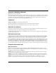
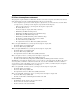
Chapter 3 Instant Internet 400 hardware installation Figure 3 Removing screws from cover of Instant Internet 400 unit 910 Po we r On Lin e Sta tus A Eth ern LA et N Eth ern Ro et ute r Sta tus B Sta tus C We Ac b tivity Dis Ac k tivity 9088FC 2 Attach the front mounting brackets to your unit using the screws provided (Figure 4).
Chapter 3 Instant Internet 400 hardware installation 3 39 Position your unit in the rack horizontally. Your unit should be facing out from the rack. 4 Align the holes in the mounting bracket with the holes in the rack. 5 Attach your unit to the front of the rack using the mounting screws and washers provided (Figure 5).
Chapter 3 Instant Internet 400 hardware installation 300867-G
Chapter 4 DIP switch settings This chapter describes the Dual Inline Pins (DIP) switch settings for your Instant Internet 400 unit, including those for normal operation, for setting the token ring speed, and for resetting your unit’s password and configuration settings. DIP switches DIP switches enable you to configure your Instant Internet unit for a particular type of operation. There are eight DIP switches on the rear panel of your unit (Figure 6). The switches are labeled left to right from 1 to 8.
Chapter 4 DIP switch settings Switch settings for normal operation Leave all switches off for normal operation, as shown in Table 4. Table 4 Switch settings for normal operation 1 2 3 4 5 6 7 8 • • • • • • • • ON OFF Switch settings for token ring speed If you need to set token ring speed to match the speed of your network, see the information in the following tables for examples of single and dual token ring switch settings.
Chapter 4 DIP switch settings 43 Dual token ring switch settings If you have a dual token ring unit and need to set the token ring speed, see one of the following tables: • • • • Table 7 (Dual token ring: 16 Mb/s Tok1 / 16 Mb/s Tok2) Table 8 (Dual token ring: 16 Mb/s Tok1 / 4 Mb/s Tok2) Table 9 (Dual token ring: 4 Mb/s Tok1 / 16 Mb/s Tok2) Table 10 (Dual token ring: 4 Mb/s Tok1 / 4 Mb/s Tok2) Table 7 Dual token ring: 16 Mb/s Tok1 / 16 Mb/s Tok2 1 ON OFF 2 • • 3 4 5 NA 6 NA 7 NA 8 NA • • NA N
Chapter 4 DIP switch settings Switch settings for special configurations During the power-up sequence, your Instant Internet 400 unit checks the settings of the switches. You can use the switches on your unit to: • • • • Reset the password (Table 11), which is useful if you forget the password. Reset the password and other user-defined system configuration (Table 12). Disable the switch settings for resetting the password and user-defined configurations (Table 13).
Chapter 4 DIP switch settings 45 Table 13 shows the switch settings to disable the switch settings for resetting the password and user-defined configurations. Table 13 Switch settings to disable switch settings for resetting the password and user-defined configurations ON 1 2 • • 3 4 5 6 7 • • • • • OFF 8 • Table 14 shows the switch settings for restoring your unit to factory default conditions.
Chapter 4 DIP switch settings Resetting your Instant Internet unit Before you reset your Instant Internet unit, be sure to back up the configuration. If you back up the configuration, you can easily restore it. For details, refer to Using the BayStack Instant Internet Management Software Version 7.11. To reset your Instant Internet unit: 1 Turn off your unit. 2 Record the current switch settings of your Instant Internet unit. 3 Set the switches to the configuration you want.
Chapter 5 LEDs: support and diagnostic functions This chapter describes how the LEDs work on your Instant Internet 400 unit and how you can use them to interpret activity on your unit. Interpreting LEDs On the front panel of the Instant Internet unit, the nine LEDs indicate failures, configuration information, and operational status. When the unit is turned on, it displays any failures as red lights.
Chapter 5 LEDs: support and diagnostic functions Recognizing single token ring speed For a single token ring unit, LED 4 shows the ring speed for 30 seconds after the unit is turned on. Table 15 shows the single token ring speed for LED 4. For more information about token ring units, refer to “Getting to know your Instant Internet 400 unit” on page 31.
Chapter 5 LEDs: support and diagnostic functions 49 LEDs during operation After the power-up sequence is complete, the LEDs indicate status and activity during operation as shown in Table 18. Table 18 LED status and appearance during operation LED # Color Power Green Appearance Meaning Solid Unit has electrical power and is turned on. Power Green and Solid Green and Amber Flashing Amber Unit is updating flash ROM. DO NOT TURN OFF until light returns to green.
Chapter 5 LEDs: support and diagnostic functions 300867-G
Appendix A Technical specifications This appendix describes the physical and environmental specifications for your Instant Internet 400 unit. Physical specifications The Instant Internet 400 unit is 17 inches wide by 15.25 inches deep and 3.875 inches high (19-inch rack-mountable, 2-rack units).
Appendix A Technical specifications 300867-G
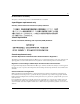
Appendix B Adapter cable pinout diagrams This appendix describes the pinout settings for the V.35 and X.21 adapter cables. Adapter cable part numbers If you ordered your Instant Internet 400 unit for use with a V.35 modem or X.21 modem, you must provide the connection cable. You can have a cable made according to the pinout diagrams in this appendix or you can order a cable from Nortel Networks using the following part numbers: • • V.35 Adapter Cable—Part Number CQ2118001 X.
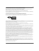
Appendix B Adapter cable pinout diagrams V.35 adapter cable Figure 7 shows the pinout settings for a V.35 modem adapter cable (part number CQ2118001) Figure 7 V.35 adapter cable pinout diagram (H) DB26 (Male) Amp Pin # 748365-1 V.
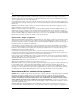
Appendix B Adapter cable pinout diagrams 55 X.21 (DCE) adapter cable Figure 8 shows the pinout settings for an X.21 modem adapter cable (part number CQ2118004). Figure 8 X.21 (DCE) adapter cable diagram. DTE DB25M DV15M (X.
Appendix B Adapter cable pinout diagrams 300867-G
Index Symbols RJ-48 connector 21 V.35 adapter 54 X.21 (DCE) adapter 55 ! Default provider 26 Numbers 100BASE-T Ethernet connection 21 10BASE-T Ethernet connection 21 26-pin connector 34, 35 3DES Encryption Module 45 56K x2/V.90 analog modem 22 9-pin connector 33 cable modem 22 CHAP 27 connection DDS 22, 27 dial-up 23 leased-line 23 PPPoE 28 T1 22, 27 V.35 27 X.
Index dual token ring unit LEDs 48 switch settings 43 E environment nonoperating 51 operating 51 Eth1 33 Eth2 33 Ethernet 100BASE-T 21 10BASE-T 21 Internet service provider ! Default provider 26 access phone number 27 additional services 28 name server 27 password 27 selecting 26 user name 27 Internet Service Provider Hotline Nortel Networks Technical Solutions Center 26 ISDN card configuration option 22 interfaces 34 NT1 22 external router 22 ISDN connection cable 21 Multilink Protocol 23 provider
Index normal operation 47 power-up sequence 47 red 47 single token ring unit 48 status 49 M modem analog 22 cable 22 DSL 22 59 R rack mounting 37 ring speed setting 42 Tok1 43, 48 Tok2 43, 48 RJ-11 connector 34 RJ-45 connector 33, 34 RJ-48 connector 35 router, external 22 Multilink Protocol (MP) 23 S N NT1 34 single token ring unit LEDs 48 switch settings 42 P size 51 package contents 21 PAP 27 passwords, resetting 44 phone cord 21 physical specifications 51 Power LED 47 PPP 23, 27 PPPoE 23, 28 pro
Index line speed 27 rate multiplier 27 setting up 27 technical publications 20 technical support 20 Telco 36 temperature nonoperating 51 operating 51 token ring 48 connection 22 LEDs 48 switch setting 42 Tok1 card 33 ring speed 48 Tok2 card 33 token ring card 33 token ring speed 16 Mb/s 42, 43 4 Mb/s 42, 43 Tok1 43 Tok2 43 U unit mounting in a rack 37 resetting 46 user-defined configurations, resetting 44 V V.35 card 35 connection 23, 27 port 0 35 port 1 35 V.35 adapter cable 54 V.