LG-Nortel ELO ES24 (LNES24) Fast Ethernet Switch User Guide
Copyright Information furnished by LG-Nortel Co.Ltd.(LG-Nortel) is believed to be accurate and reliable. However, no responsibility is assumed by for its use, nor for any infringements of patents or other rights of third parties which may result from its use. No license is granted by implication or otherwise under any patent or patent rights of LG-NORTEL. LG-NORTEL reserves the right to change specifications at any time without notice. Copyright © 2008 by LG-NORTEL Co.Ltd.
LIMITED WARRANTY Limited Warranty Statement: LG-Nortel warrants the Products, excluding consumable items to be free from defective design attributable to LG-Nortel, defective material or faulty workmanship and will conform to the Specifications for twelve (12) months from the date of Customer acceptance of the Product.
WARRANTIES EXCLUSIVE: IF AN LG-NORTEL PRODUCT DOES NOT OPERATE AS WARRANTED ABOVE, CUSTOMER.S SOLE REMEDY SHALL BE REPAIR OR REPLACEMENT OF THE PRODUCT IN QUESTION, AT LG-NORTEL’S OPTION. THE FOREGOING WARRANTIES AND REMEDIES ARE EXCLUSIVE AND ARE IN LIEU OF ALL OTHER WARRANTIES OR CONDITIONS, EXPRESS OR IMPLIED, EITHER IN FACT OR BY OPERATION OF LAW, STATUTORY OR OTHERWISE, INCLUDING WARRANTIES OR CONDITIONS OF MERCHANTABILITY AND FITNESS FOR A PARTICULAR PURPOSE.
COMPLIANCES FCC - Class A This equipment has been tested and found to comply with the limits for a Class A digital device, pursuant to Part 15 of the FCC Rules. These limits are designed to provide reasonable protection against harmful interference in a residential installation. This equipment generates, uses and can radiate radio frequency energy and, if not installed and used in accordance with instructions, may cause harmful interference to radio communications.
voltage limits and the Amendment Directive 93/68/EEC.
Please read the following safety information carefully before installing the Switch: WARNING: Installation and removal of the unit must be carried out by qualified personnel only. • This guide is intended for use by network administrators who are responsible for setting up and installing network equipment; consequently it assumes a basic working knowledge of LANs (Local Area Networks). • The unit must be connected to an earthed (grounded) outlet to comply with international safety standards.
France and Peru only This unit cannot be powered from IT. supplies. If your supplies are of IT type, this unit must be powered by 230 V (2P+T) via an isolation transformer ratio 1:1, with the secondary connection point labelled Neutral, connected directly to earth (ground). †Impédance à la terre Power Cord Set U.S.A. and Canada The cord set must be UL-approved and CSA certified. The minimum specifications for the flexible cord are: - No. 18 AWG - not longer than 2 meters, or 16 AWG.
Warnings and Cautionary Messages Warning: This product does not contain any serviceable user parts. Warning: Installation and removal of the unit must be carried out by qualified personnel only. Warning: When connecting this device to a power outlet, connect the field ground lead on the tri-pole power plug to a valid earth ground line to prevent electrical hazards. Caution: Wear an anti-static wrist strap or take other suitable measures to prevent electrostatic discharge when handling this equipment.
Environmental Statement The manufacturer of this product endeavours to sustain an environmentally-friendly policy throughout the entire production process. This is achieved though the following means: • Adherence to national legislation and regulations on environmental production standards. • Conservation of operational resources. • Waste reduction and safe disposal of all harmful un-recyclable by-products. • Recycling of all reusable waste content.
TABLE OF CONTENTS Introduction Features and Benefits Front Panel LED’s Front panel Rear Panel Installing the Switch Package Contents Selecting a Site Instructions Troubleshooting Diagnosing Switch Indicators Cables Cable Specifications Product Specifications 1 1 2 3 3 4 4 4 5 7 7 8 8 10
INTRODUCTION The LNES24 is a 24-port Fast Ethernet switch. The 10BASE-T/100BASE-TX ports deliver dedicated 10/100 Mbps links to each attached LAN segment – all with conventional cabling and adapters. Auto-negotiation is used to select the optimal communication mode for each connection. Auto-sensing is used to select the optimal transmission speed for each connection. With store-and-forward switching and flow control, maximum data integrity is always maintained, even under heavy loading.
Front Panel LEDs The front panel of the switch provides a link status LED for each RJ-45 port. In addition, the front panel also contains status LEDs for “at-a-glance” system monitoring. The following table details the functions of the various indicators: Port and Switch Status LEDs LED Condition Status Power On Green The switch is receiving power. On The port has established a valid network connection. Flashing Traffic is passing through the port.
INSTALLING THE SWITCH Before installing the switch, verify that you have all the items listed under “Package Contents.” Note that the switch can be installed on any suitably large flat surface or in a standard EIA 19-inch rack.
• • Make sure twisted-pair cable is always routed away from power lines, fluorescent lighting fixtures and other sources of electrical interference such as radios, transmitters, etc. Make sure that a properly grounded power outlet is within 2.44 meters (8 feet) of the switch and is powered from an independent circuit breaker. As with any equipment, using a filter or surge suppressor is recommended. Instructions 1.
4. Cascading Switches and Other Network Devices: All the ports on the switch support automatic MDI/MDI-X configuration for cable connections. This allows you to use straight-through cable to connect to other switches or hubs from any port on the switch. No crossover cables or other device settings are needed. See the Cable Specifications. Caution: Do not plug a phone jack connector into any RJ-45 port. This the switch.
TROUBLESHOOTING Diagnosing Switch Indicators 1. Symptom Power LED does not light after power on. Probable Causes o AC power cord may be defective. Possible Solutions o Check for loose connections. o Check the power outlet by using it for another device. o Replace the AC power cord. 2. Symptom Link LED does not light after connection is made. Probable Causes o Switch port, network card or cable may be defective. Possible Solutions o Check that the switch and attached device are both powered on.
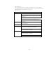
CABLES Cable Specifications Cable 10BASE-T 100BASE-TX Cable Types and Specifications Type Max. Length 2-pair Cat. 3 or better 100-ohm 100 m (328 ft) UTP 2-pair Cat. 5 or better 100-ohm 100 m (328 ft) UTP Connector RJ-45 RJ-45 10BASE-T/100BASE-TX Pin Assignments Caution: DO NOT plug a phone jack connector into any RJ-45 port. Use only twisted-pair cables with RJ-45 connectors that conform with FCC standards.
The table below shows the 10BASE-T/100BASE-TX MDI-X and MDI port pinouts.
PRODUCT SPECIFICATIONS LNES24 Fast Ethernet Switch Standards Conformance IEEE 802.3-2002 Ethernet, Fast Ethernet Full-duplex flow control Communication Rate 10 and 100Mbps Communication Mode Full or half duplex at 10/100 Mbps Media Supported 10BASE-T: 100-ohm Category 3 or better twisted-pair 100BASE-TX: 100-ohm Category 5 or better twisted pair Number of Ports LNES24: 24 RJ-45 10/100 BASE-T ports Indicator Panel Power Ports: Link/Act, 10/100M Dimensions 28x17.3x4.4 cm (11x6.8x1.7 in.) Weight LNES24: 1.
Memory Buffer LNES24: 1.