
Digital Modem Installation Guide


84 Appendix
CTA 500
dm
On Line Guide P0873832 Issue 05
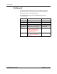
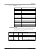
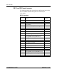
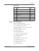
DB-25 and DB-9 signal summary
The following tables show which DB-25 and DB-9 pins are used by
the CTA 500dm and what the signals are used for by the
CTA 500dm.
DB-25 connection
DB-25
pin
RS-232
function
CTA 500
dm
function
1 Shield Shield
2 Transmitted Data TD
3 Received Data RD
4 Request to Send/Ready for Receiving RTS
5 Clear to Send CTS
6 DCE Ready DSR
7 Signal Common GND
8 Received Line Signal Detector DCD
12 Secondary Received Line Signal/Detector/
Data Signal Rate Selector (DCE Source)
–
13 Secondary Clear to Send –
14 Secondary Transmitted Data –
16 Secondary Received Data –
18 Local Loopback –
19 Secondary Request to Send –
20 DTE Ready DTR
22 Ring Indicator RI
23 Data Signal Rate Selector (DCE/DTE Source) –
24 Transmitter Signal Element Timing (DTE Source) no
25 Test Mode no