Nortel Communication Server 1000 Communication Server 1000M and Meridian 1 Large System Overview Release: 5.5 Document Revision: 02.05 www.nortel.com NN43021-110 .
Nortel Communication Server 1000 Release: 5.5 Publication: NN43021-110 Document status: Standard Document release date: 30 September 2008 Copyright © 2003-2008 Nortel Networks All Rights Reserved. Sourced in Canada LEGAL NOTICE While the information in this document is believed to be accurate and reliable, except as otherwise expressly agreed to in writing NORTEL PROVIDES THIS DOCUMENT "AS IS" WITHOUT WARRANTY OR CONDITION OF ANY KIND, EITHER EXPRESS OR IMPLIED.
. Contents New in this Release Other 5 Revision History 5 How to get help Getting Getting Getting Getting help help help help 5 7 from the Nortel Web site 7 over the telephone from a Nortel Solutions Center 7 from a specialist by using an Express Routing Code 7 through a Nortel distributor or reseller 8 Introduction 9 Subject 9 Applicable systems 9 Intended audience 10 Conventions 10 Related information 11 Product description 13 Contents 13 Introduction 13 System options 15 CS 1000M HGand Me
Common control complex 35 Network interface 39 Intelligent Peripheral Equipment Terminal equipment 46 Power equipment 47 Signaling Server 49 Software architecture 55 Firmware 56 Software 56 Office data 56 Resident programs 56 Nonresident programs 57 Configuration options 58 Fiber Remote IPE 58 Carrier Remote IPE 61 Branch Office 62 Geographic Redundancy 62 43 Nortel Communication Server 1000 Communication Server 1000M and Meridian 1 Large System Overview NN43021-110 02.
. New in this Release There have been no updates to the document in this release. Other Revision History September 2008 Standard 02.05. This document is up-issued to add content about FIJI redesign in System modules chapter. September 2008 Standard 02.04. This document is issued to support Communication Server 1000 Release 5.5. July 2008 Standard 02.03. This document is issued to support Communication Server 1000 Release 5.5. December 2007 Standard 02.02.
New in this Release Nortel Communication Server 1000 Communication Server 1000M and Meridian 1 Large System Overview NN43021-110 02.05 Standard 30 September 2008 Copyright © 2003-2008 Nortel Networks .
. How to get help This chapter explains how to get help for Nortel products and services. Getting help from the Nortel Web site The best way to get technical support for Nortel products is from the Nortel Technical Support Web site: www.nortel.com/support This site provides quick access to software, documentation, bulletins, and tools to address issues with Nortel products.
How to get help Getting help through a Nortel distributor or reseller If you purchased a service contract for your Nortel product from a distributor or authorized reseller, contact the technical support staff for that distributor or reseller. Nortel Communication Server 1000 Communication Server 1000M and Meridian 1 Large System Overview NN43021-110 02.05 Standard 30 September 2008 Copyright © 2003-2008 Nortel Networks .
. Introduction This document is a global document. Contact your system supplier or your Nortel representative to verify that the hardware and software described are supported in your area. Subject WARNING Before a Large System can be installed, a network assessment must be performed and the network must be VoIP-ready. If the minimum VoIP network requirements are not met, the system will not operate properly.
Introduction • Communication Server 1000M Multi Group (CS 1000M MG) CP PII, CP PIV • • • • Meridian 1 PBX 11C Chassis Meridian 1 PBX 11C Cabinet Meridian 1 PBX 61CCP PII, CP PIV Meridian 1 PBX 81CCP PII, CP PIV Note: When upgrading software, memory upgrades may be required on the Signaling Server, the Call Server, or both. System migration When particular Meridian 1 systems are upgraded to run CS 1000 Release 5.5 software and configured to include a Signaling Server, they become CS 1000M systems.
Related information 11 The following systems are referred to generically as "Large System": • • • • Communication Server 1000M Single Group (CS 1000M SG) Communication Server 1000M Multi Group (CS 1000M MG) Meridian 1 PBX 61CCP PII, CP PIV Meridian 1 PBX 81CCP PII, CP PIV Related information This section lists information sources that relate to this document.
Introduction Nortel Communication Server 1000 Communication Server 1000M and Meridian 1 Large System Overview NN43021-110 02.05 Standard 30 September 2008 Copyright © 2003-2008 Nortel Networks .
. Product description Contents This section contains information on the following topics: “Introduction” (page 13) “System options” (page 15) “CS 1000M HGand Meridian 1 Option 51C” (page 15) “CS 1000M SGand Meridian 1 PBX 61C CP PIV” (page 18) “CS 1000M MGand Meridian 1 PBX 81C CP PIV” (page 21) “System modules” (page 24) “NT4N41 Core/Network module” (page 24) “NT5D21 Core/Network module” (page 26) “NT8D35 Network module” (page 27) “Fiber Network Fabric” (page 29) “NT8D37 Intelligent Peripheral Equipme
Product description All Large Systems consist of Universal Equipment Modules (UEM) stacked one on top of another to form a column. Each column contains a pedestal, a top cap, and up to four modules. A system can have one column or multiple columns. Each UEM is a self-contained unit that houses a card cage and backplane, power and ground cabling, power units, input/output (I/O) panels, circuit cards, and cables.
System options 15 System options This document includes information on the following Large Systems: • CS 1000M HGand Meridian 1 Option 51C: enhanced common control complex, single CPU, and one half network group • CS 1000M SG, Meridian 1 PBX 61C CP PIV, and Meridian 1 Option 61C: enhanced common control complex, dual CPU, and one full-network group • CS 1000M MG, Meridian 1 PBX 81C CP PIV, Meridian 1 Option 81, and Meridian 1 Option 81C: enhanced common control complex, dual CPU, and multiple-networ
Product description Figure 1 Meridian 1 Option 51C Figure 2 CS 1000M HG Nortel Communication Server 1000 Communication Server 1000M and Meridian 1 Large System Overview NN43021-110 02.05 Standard 30 September 2008 Copyright © 2003-2008 Nortel Networks .
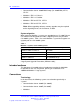
System options Table 2 Specifications for CS 1000M HGand Meridian 1 Option 51C System characteristics: Maximum number of ports • 1000 Input voltage • 208 V AC or –48 V DC Number of CPUs • 1 Number of network loops • 16 Release 25 • NT5D10 CP or NT5D03 CP card Succession 3.0 • CP3 NT5D10 CP or CP4 NT5D03 card CS 1000 Release 4.
Product description Table 2 Specifications for CS 1000M HGand Meridian 1 Option 51C (cont’d.) Top cap (one per column) • Thermostat harness • Air probe harness CS 1000M SGand Meridian 1 PBX 61C CP PIV The CS 1000M SGand the Meridian 1 PBX 61C CP PIVare dual-CPU systems with standby processing capability, fully redundant memory, and a full-network group. Two cPCI Core/Network modules and one IPE module are required. Additional IPE modules and application modules can be used.
System options Figure 4 CS 1000M SG Table 3 "Specifications for CS 1000M SGand Meridian 1 PBX 61C CP PIV" (page 19) lists the specifications for CS 1000M SGand Meridian 1 PBX 61C CP PIV. Table 3 Specifications for CS 1000M SGand Meridian 1 PBX 61C CP PIV System characteristics: Maximum number of ports • 2000 Input voltage • • • 208 V AC or –48 V DC Release 25 • NT5D10 CP or NT5D03 CP card Succession 3.0 • CP3 NT5D10 or CP4 NT5D03 card CS 1000 Release 4.
Product description Table 3 Specifications for CS 1000M SGand Meridian 1 PBX 61C CP PIV (cont’d.
System options 21 CS 1000M MGand Meridian 1 PBX 81C CP PIV The CS 1000M MGand Meridian 1 PBX 81Care dual-CPU systems with standby processing capabilities, fully-redundant memory, and up to eight full network groups. These systems are equipped with two redundant input/output processor and disk drive unit combination packs.
Product description Figure 6 CS 1000M MG Table 4 "Specifications for CS 1000M MGand Meridian 1 Option 81C CP PIV" (page 22) lists specifications for the Meridian 1 PBX 81C CP PIV. Table 4 Specifications for CS 1000M MGand Meridian 1 Option 81C CP PIV System characteristics: Maximum number of ports • 10 000 Input voltage • 208 V AC or –48 V DC Number of CPUs • 2 (redundant) Number of network loops • 256 Memory • 128 MB • 256 MB • CP3 NT5D10, required for CS 1000 Release 4.
System options Table 4 Specifications for CS 1000M MGand Meridian 1 Option 81C CP PIV (cont’d.
Product description Table 4 Specifications for CS 1000M MGand Meridian 1 Option 81C CP PIV (cont’d.) Pedestal (one per column) Top cap (one per column) • System monitor • Power Distribution Unit (PDU) • Blower unit • Thermostat harness • Air probe harness System modules Each type of module is available in AC-powered and DC-powered versions (except the NT8D36 InterGroup module that does not require power).
System modules 25 Figure 7 "NT4N41 cPCI Core/Network module" (page 25) illustrates an NT4N41 Core/Network module. Core side The Core side of the module contains the circuit cards that process calls, manage network resources, store system memory, maintain the user database, and monitor the system. These circuit cards also provide administration interfaces through a terminal, modem, or enterprise IP network.
Product description The double slot FIJI (NTRB33AF) card is installed in slots 2 and 3 on the Network module, while the single slot FIJI (NTRB33BBE5) card is installed in slot 2 on the Network module. NT5D21 Core/Network module This module provides common control and network interface functions in CS 1000M SG, CS 1000M MG, CS 1000M HG, Meridian 1 Option 51C, Meridian 1 Option 61C, and Meridian 1 Option 81C.
System modules 27 Figure 8 NT5D21 Core/Network module NT8D35 Network module This module provides the network switching functions in the Meridian 1 Option 81C, Meridian 1 PBX 81C CP PIV, and CS 1000M MG. Two Network modules are required to make a full network group of 32 loops. A maximum of 16 Network modules (eight network groups) can be configured in the Meridian 1 Option 81C, CS 1000M MG, and Meridian 1 PBX 81C CP PIV.
Product description Figure 9 NT8D35 Network module The Network module can be used as a PRI/DTI expansion module. The number of PRI/DTI expansion modules that can be used is determined by traffic considerations. Figure 10 "NT8D35 Network module configured for PRI/DTI expansion" (page 29) shows the card slot configuration when the Network module is used for PRI/DTI expansion.
System modules 29 Figure 10 NT8D35 Network module configured for PRI/DTI expansion Fiber Network Fabric Fiber Network Fabric extends and enhances the five-group network architecture to 8 non-blocking (inter-group) Network groups, with a resulting expansion in network capacity to 8000 timeslots available for Intergroup traffic. The Meridian 1 PBX 61C CP PIVcan be upgraded to a Meridian 1 PBX 81C CP PIVwith Fiber Network Fabric.
Product description Figure 11 Four group Fiber Network Fabric configuration NT8D37 Intelligent Peripheral Equipment module The Intelligent Peripheral Equipment (IPE) module provides the interface between network switching and IPE cards, such as intelligent line and trunk cards, in all Large Systems. The IPE module houses one NT8D01 Controller Card, which is the peripheral equipment controller, and up to 16 IPE cards, supporting up to 512 terminal numbers (256 voice and 256 data).
System modules 31 Figure 12 NT8D37 IPE module Fiber Remote IPE module This module provides fiber-optic links between the network functions in a Large System and the peripheral controller functions in the Fiber Remote IPE. A floor-standing column or wall-mounted cabinet is installed at the remote site and is connected to the Large System using fiber-optic links. The Fiber Remote IPE provides Large Systems functionality with the installation of only IPE modules and IPE cards at a distant site.
Product description Nortel Communication Server 1000 Communication Server 1000M and Meridian 1 Large System Overview NN43021-110 02.05 Standard 30 September 2008 Copyright © 2003-2008 Nortel Networks .
. System architecture Contents This section contains information on the following topics: “Hardware architecture” (page 34) “Common control complex” (page 35) “Network interface” (page 39) “Intelligent Peripheral Equipment” (page 43) “Terminal equipment” (page 46) “Power equipment” (page 47) “Signaling Server” (page 49) “Software architecture” (page 55) “Firmware” (page 56) “Software” (page 56) “Office data” (page 56) “Resident programs” (page 56) “Nonresident programs” (page 57) “Configuration options
System architecture Hardware architecture CS 1000M and Meridian 1systems are circuit-switched digital systems that provide voice and data transmission. The internal hardware is divided into the following functional areas (see Figure 13 "Large System basic architecture" (page 35) on Figure 13 "Large System basic architecture" (page 35)): • Common Control Complex (Common Equipment) circuit cards provide the processor control, software execution, and memory functions of the system.
Hardware architecture 35 Figure 13 Large System basic architecture Common control complex The processor is the common control complex of the system. It provides the sequences to process voice and data connections, monitor call activity, and perform system administration and maintenance. The processor communicates with the network interface over a common control bus that carries the flow of information.
System architecture • the disk drive unit that provides mass storage for operating programs and data • I/O interfaces that provide an information exchange between the user and the system CS 1000M and Meridian 1"core" processor cards support extensive networking and provide intensive use of software features and applications, including call centers of up to 1000 agents.
Hardware architecture 37 In the CS 1000M SGand Meridian 1 PBX 61C CP PIVCore/Network module, the core side houses the following equipment: • • • • • one Call Processor Pentium IV® (CP PIV) card one System Utility (Sys Util) card one Core-to-Network Interface (cCNI) cards one System Utility Transition (Sys Util Trans) card four cCNI Transition (cCNI Trans) cards Cabling between the CP cards allows memory shadowing and dual-CPU operation.
System architecture Core/Net modules diagnose faults in field-replaceable units for all core hardware, including cables. In case of a failure, a message appears on the system terminal and on the LCD of the faceplate of the utility card. Core to Core Ethernet connection (LAN1 to LAN2) between the CP PIV cards allows memory shadowing and dual-CPU operation. The cCNI Transition cards connect the Core module cards to the 3PE cards in the Network modules.
Hardware architecture 39 The System Utility card supports Card ID. The card provides an interface between the security device and the computer, and an interface between the XSM and display panel for each Core/Net card cage. This card also includes a switch on the faceplate to enable or disable the Core cards. The System Utility Transition card provides connections for the security device, the system monitor, and the status panel.
System architecture Network organization Network loops are organized into groups. A system is generally configured as one of the following: • • • a half group system (CS 1000M HG) that provides up to 16 loops a single group system (CS 1000M SG) that provides up to 32 loops a multi-group system (CS 1000M MG) that provides up to 256 loops The Fiber Junctor Interface (FIJI) cards in the Network modules are connected with fiber-optic cables to form a Dual Ring Fiber Network.
Hardware architecture 41 Superloop network configurations By combining four network loops, the superloop network card makes 120 timeslots available to IPE cards. Compared to regular network loops, the increased bandwidth and a larger pool of timeslots increases network traffic capacity for each 120-timeslot bundle by 25 percent (at a P0.1 grade of service). The NT8D37 IPE module is divided into segments numbered 0–3 of four card slots each (see Figure 15 "Superloop segments in the IPE module" (page 41)).
System architecture • four segments per superloop requires one superloop network card and one controller-2 card • eight segments per superloop requires one superloop network card and two controller-2 cards • one segment per superloop/three segments on a second superloop requires two superloop network cards and one controller-2 card • two segments per superloop/six segments on a second superloop requires two superloop network cards and two controller-2 cards As an example of a superloop configura
Hardware architecture 43 Figure 16 Eight segments per superloop Intelligent Peripheral Equipment Using pulse code modulation (PCM), Intelligent Peripheral Equipment (IPE) converts analog signals to digital signals before switching is performed by the network. This conversion method samples the amplitude of the analog signal at a rate of twice the highest signal frequency, then converts the amplitude into a series of coded pulses. For telecommunications, the PCM-sampling frequency standard is 8 kHz.
System architecture IPE is associated with network loops. IPE cards are supported by NT8D04 Superloop Network Card loops. The traffic requirements of all IPE cards provisioned on a particular network loop must match the traffic capacity of that loop.
Hardware architecture 45 Table 5 Intelligent Peripheral Equipment cards (cont’d.
System architecture Any medium that conforms to the DS-1 format (1.544 Mbps) can be used to link local and remote sites, including digital microwave radio and fiber-optic transmission systems. Terminal equipment Large Systems support a wide range of telephones, including multiple-line and single-line telephones, as well as digital telephones with key and display functions and data transmission capabilities.
Hardware architecture 47 Meridian attendant consoles support attendant message center options. The attendant console can be connected to a PC to provide electronic directory, dial-by-name, and text messaging functions. All call processing features can be accessed using the computer keyboard. Power equipment Large Systems provide a modular power distribution architecture.
System architecture power" (page 48)). An AC-powered system that does not require long-term backup can benefit from a UPS with short-term backup because the UPS typically provides power conditioning during normal operation, as well as reserve power during short outages or blowouts.
Hardware architecture 49 Figure 18 ExternalDC-power architecture with reserve power Candeo DC power system The Candeo platform provides a simple, quick-to-deploy, and easy-to-operate power solution. Based upon modular building blocks (rectifiers, System Manager, DC distribution, and battery connection modules), the system is designed to power -48 V DC applications.
System architecture CS 1000 Release 5.5 introduces three new servers that can host a CS 1000 Release 5.5 Signaling Server: • • • “Nortel Common Processor Pentium Mobile server” (page 50) “International Business Machines X306m server” (page 51) “Hewlett Packard DL320-G4 server” (page 51) The Signaling Server has both an ELAN and TLAN network interface. The Signaling Server communicates with the Call Server through an ELAN subnet. The Signaling Server is mounted in a 19-inch rack.
Hardware architecture 51 The Nortel CP PM server has the following components: • • • • • • • • Intel Pentium M processor (1.4 Ghz) internal hard drive hot-pluggable Compact Flash (CF) card slot in the faceplate 2 GB of SDRAM One 1 GB/s Ethernet port Two 100BaseT Ethernet ports Two serial ports One USB port For more information about installing and configuring the Nortel CP PM server as a Signaling Server, seeSignaling Server Installation and Commissioning (NN43001-312), .
System architecture The HP DL320-G4 1U server has the following components: • • • • • • • • Intel Pentium 4 processor (3.6 GHz) Two 80 GB SATA Hard drives (1 configured) 4 GB PC2-4200 ECC DDR2 SDRAM (2 GB configured Two 10/100/1000BaseT Ethernet ports One CD-R/DVD ROM drive One serial port Three USB ports For more information about installing and configuring the HP DL320-G4 server as a Signaling Server, see Signaling Server Installation and Commissioning (NN43001-312), .
Hardware architecture 53 Network Routing Service NRS for CS 1000 Release 5.5 software is offered in two versions: a SIP Redirect Server NRS and a SIP Proxy NRS. The SIP Redirect Server NRS is hosted either co-resident with Signaling Server applications, or in a stand-alone mode on a dedicated Common Processor Pentium Mobile (CP PM) server running the VxWorks™ real-time operating system. There are no changes to the SIP Redirect Server NRS in CS 1000 Release 5.5.
System architecture The H.323 Gatekeeper and the SIP Redirect Server can reside on the same Signaling Server. Examples of H.323 and SIP-compatible endpoints needing the services of the NRS are CS 1000E. The NRS also supports endpoints that do not support H.323 Registration, Admission, and Status (RAS) or SIP registration with the NRS. Note: Systems that do not support H.323 RAS procedures and H.323 Gatekeeper procedures are referred to as non-RAS or static endpoints.
Software architecture 55 Element Manager Element Manager is a software application that provides a web interface to support administration of system components, including the Signaling Server. With Element Manager, single web pages provide access to information traditionally spread throughout multiple overlays.
System architecture Call processing, maintenance, and administration are controlled by software programs stored either as firmware programs, as software programs resident in system memory, or as nonresident programs on disk. The information that describes system configuration and associated IPE is called office data. This data resides in the system memory and on disk.
Software architecture 57 All software programs, including the nonresident programs listed in the following section are resident in, and accessible from, the memory on the cards listed above. Nonresident programs Nonresident programs are stored on data disks and loaded into the overlay area of system memory to perform specific tasks. They are removed from the overlay area when no longer required.
System architecture Traffic All systems are equipped with traffic data accumulation programs. There is also a resident traffic print program that examines the schedules, transfers data from accumulating to holding registers in accordance with schedules, and prints the traffic data. In addition, there is a traffic program used to query and modify schedules, options, and thresholds. Equipment data dump After making service changes, the changes must be saved to disk in order to save them.
Configuration options 59 In a distributed system, subscriber connections are the same at local IPE modules as they are at Remote IPE modules or small cabinets. Furthermore, because Remote IPE equipment uses common and network equipment from the local system, subscriber functions and features are the same at local and remote sites. Figure 19 "Large System to Remote IPE site" (page 59) illustrates the fiber-optic connection between a local system and remote system.
System architecture The Fiber Remote Multi-IPE Interface links the local and remote systems using a fiber-optic link over a single-mode optical fiber.
Configuration options 61 Carrier Remote IPE The Carrier Remote IPE provides functionality by installing only IPE modules and IPE cards at a distant site. The Remote IPE shares the system’s Common and Network Equipment to provide the same functions and features to remote subscribers that are available to local system subscribers. A floor-standing column or a wall-mounted cabinet Carrier Remote IPE is installed at the remote site and is connected to the Meridian 1 Large System using T1 or E1 connection.
System architecture Branch Office The Branch Office feature extends system features from a main office to one or more branch offices. A branch office is an MG 1000B Core connected to an IP PBX at the main office over an enterprise IP network or over a WAN. This configuration enables a secondary location to centralize the call processing of its IP-based communications network. The Call Server at the main office provides the call processing for the IP Phones in both the main office and branch offices.
. List of terms AC Alternating Current analog A process that models information in the form of a continuously varying parameter such as current, voltage, or phase. analog signal A signal that varies in a continuous manner such as voice or music. An analog signal can be contrasted with a digital signal, which represents only discrete states. The signal emitted by a data telephone has both analog and discrete characteristics.
List of terms CBT Core Bus Terminator CE Common Equipment Central Office (CO) The site where a telephone company terminates customer lines and houses the switching equipment that interconnects those lines. central processing unit (CPU) The main portion of a computer that contains the primary storage, arithmetic and logic units, and the control unit (may also mean a mainframe computer). circuit cards Cards which carry the electronics for particular functions (such as memory and switching functions).
cPCI Transition card Peripheral Component Interconnect Transition Card. Connects the Core module cards to the 3PE cards in the Network modules. CP PIV® The successor to the Pentium II from Intel. Pentium IV refers to the Pentium IV CPU chip.
List of terms ISDN Integrated Services Digital Network line A communication channel or circuit; an electrical path. loop A bidirectional path between network equipment and peripheral equipment. module power supplies Individual power units that generate the different DC voltages required by the cards installed in each module. Network Equipment A hardware subsystem that provides digital multiplexed switching for voice, data, and signaling paths.
read-only memory (ROM) Storage system or computer memory that is "burned into" the microprocessor chip and can be read, but not written to or modified. ROM is nonvolatile memory. redundancy The duplication of software, or hardware, or both (such as redundant CPUs) used as a standby in case one fails. SDI Serial Data Interface. A family of cards equipped with SDI ports provide the I/O interface for the CS 1000M Large Systemand Meridian 1 Large System.
List of terms top cap A top cap is mounted on the top module of each column. It provides airflow exits, EMI/RFI shielding, I/O cable entry and exit, and overhead cable-rack mounting. The top cap covers thermal sensor assemblies for the column. trunk A single circuit between two points, both of which are switching centers or individual distribution points.
Nortel Communication Server 1000 Communication Server 1000M and Meridian 1 Large System Overview Copyright © 2003-2008 Nortel Networks All Rights Reserved. Release: 5.5 Publication: NN43021-110 Document status: Standard Document revision: 02.05 Document release date: 30 September 2008 To provide feedback or to report a problem in this document, go to www.nortel.com/documentfeedback. www.nortel.