
Computer Hardware Installation Guide

Architecture 981
Note: The ON position for all the switches is towards the bottom of the
card. This is indicated by a white dot printed on the board adjacent to
the bottom left corner of each individual switch.
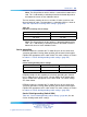
The line interface provides for the use of either 75 ohms coaxial or 120
ohms twisted pair cable. The impedance is selected by SW2, as shown in
Table 410 "Impedance matching switch settings" (page 981).
Table 410
Impedance matching switch settings
Cable Type SW 2-1
75 ohms Down (On)
120 ohms Up (Off)
Note: The ON position for all the switches is toward the bottom of the
card. This is indicated by a white dot printed on the board next to the
bottom left corner of each individual switch.
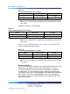
Carrier grounding
NTBK50 enables the shield of the Tx and/or Rx pairs of the carrier to be
selectively grounded. Closing (down position) the on-board switch applies
FGND to the appropriate carrier cable shield. The switch settings are shown
in Table 411 "Carrier Shield grounding switch settings" (page 981).
Table 411
Carrier Shield grounding switch settings
Switch Down (On) Up (Off)
SW 4 – 1 Rx – FGND Rx – OPEN
SW 4 – 2 Tx – FGND Tx – OPEN
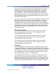
NTBK50 provides for the capability of selectively grounding the shield of
the Tx and/or Rx pairs of the carrier. Closing (down) the on-board switch
applies FGND to the appropriate carrier cable shield. The switch settings
are shown below.
NTBK50 enables the shield of the Tx and/or Rx pairs of the carrier to be
selectively grounded. Closing (down position) the on-board switch applies
FGND to the appropriate carrier cable shield. The switch settings are shown
in Table 414 "Carrier Shield grounding switch settings" (page 982).
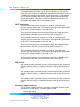
Carrier Shield grounding (Switch SW4)
Table 412 "Carrier Shield grounding switch settings" (page 982) lists the
Carrier Shield ground switch settings.
Nortel Communication Server 1000
Circuit Card Reference
NN43001-311 01.04 Standard
Release 5.0 23 May 2008
Copyright © 2003-2008, Nortel Networks
.