
Computer Hardware Installation Guide

Architecture 939
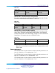
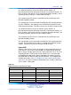
Table 390
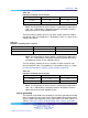
Impedance matching switch selection
Cable On Off
75 ohms S2 S1
120 ohms S1 S2
Note: The ON position for all the switches is towards the bottom of the
card. This is indicated by a white dot printed on the board next to the
bottom left corner of each individual switch.
The line interface provides for the use of either 75ohm coaxial or 120ohm
twisted pair cable. The impedance is selected by a switch, as shown in the
settings table below.
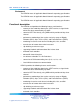
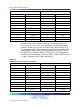
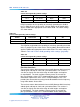
Table 391
Impedance matching switch selection
Cable On Off
75 Ohm S2 S1
120 Ohm S1 S2
Note: The ON position for all the switches is towards the bottom of the
card. This is indicated by a white dot printed on the board adjacent to
the bottom left corner of each individual switch.
The line interface provides for the use of either 75 ohms coaxial or 120
ohms twisted pair cable. The impedance is selected by a switch, as shown
in Table 392 "Impedance matching switch selection" (page 939).
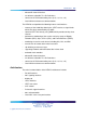
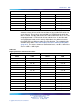
Table 392
Impedance matching switch selection
Cable On Off
75 ohms S2 S1
120 ohms S1 S2
Note: The ON position for all the switches is towards the bottom of the
card. This is indicated by a white dot printed on the board next to the
bottom left corner of each individual switch.
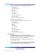
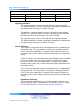
Carrier grounding
The NTAK79 card provides the capability of selectively grounding the shield
of the Tx and/or Rx pairs of the carr ier. Closing (down) the on-board switch
applies FGND to the appropriate carrier cable shield. The switch settings are
shown in Table 393 "Carrier shield grounding switch settings" (page 940).
Nortel Communication Server 1000
Circuit Card Reference
NN43001-311 01.04 Standard
Release 5.0 23 May 2008
Copyright © 2003-2008, Nortel Networks
.