
Computer Hardware Installation Guide

Physical description 931
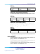
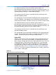
Table 384
Switch SW2
Cable Type SW 2-1 SW 2-2
75 ohms Up (Off) Down (On)
120 ohms Down (On) Up (Off)
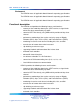
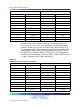
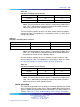
Switch SW3 - Clock Controller Configuration
This switch enables/disables (H/W) the on-board Clock Controller. Disable
the SW 3-2 if the on-board clock controller is not in use.
Table 385
Switch SW3
Switch Down (On) Up (Off)
Note
SW 3-1
——
Spare
SW 3-2 Disabled Enabled
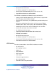
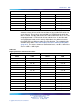
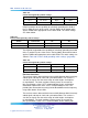
Switch SW4 - Carrier Shield Grounding
This switch enables for the selective grounding of the Tx / Rx pairs of the
carrier cable. Closing the switch (down position) applies Frame Ground
(FGND) to the coaxial carrier cable shield, creating a 75 ohms unbalanced
configuration. This applies only to the NTBK05CA cable.
Table 386
Switch SW4
Switch Down (On) Up (Off)
SW 4-1 Rx – FGND Rx – OPEN
SW 4-2 Tx – FGND Tx – OPEN
Note: The usual method is to ground the outer conductor of the receive
coaxial signal.
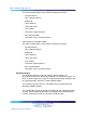
Power requirements
The NTAK79 obtains its power from the backplane, drawing maximums of 2
A on +5 V, 50 mA on +12 V and 50 mA on –12 V.
The NTAK79 obtains its power from the backplane, drawing maximums of 2
amps on +5 V, 50 mA on +12 V and 50 mA on -12 V.
The NTAK79 obtains its power from the backplane, drawing maximums of 2
A on +5 V, 50 mA on +12 V and 50 mA on –12 V.
Nortel Communication Server 1000
Circuit Card Reference
NN43001-311 01.04 Standard
Release 5.0 23 May 2008
Copyright © 2003-2008, Nortel Networks
.