
Computer Hardware Installation Guide
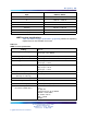
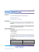

850 NTAK02 SDI/DCH card
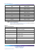
Table 337
Switch settings
Port 0 Port 1
SW 1-1 SW 1-2
SDI (not supported) DCH OFF OFF
SDI (not supported) DCH OFF ON
—
ESDI ON ON
Port 2 Port 3
SW 1-3 SW 1-4
SDI (not supported) DCH OFF OFF
SDI (not supported) DCH OFF ON
—
ESDI ON ON
Note: Digital Pr ivate Network Signaling System DPNSS can replace
the DCH function in the U.K.
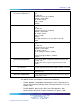
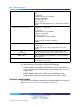
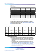
Two ports offer the option for DTE/DCE configuration. This option is
selected from a jumper on the card. Table 338 "Jumper settings" (page
850) shows the jumper settings.
Table 338
Jumper settings
Port
Jumper
location
Strap for
DTE
Strap for
DCE
Jumper
location RS422 RS232
0
J10 C - B B - A
1
J7 J6
C-B
C-B
B-A
B-A
J9
J8
C-B
C-B
B-A
B-A
2
J5 C - B B - A
3
J4
J3
C-B
C-B
B-A
B-A
J2
J1
C-B
C-B
B-A
B-A
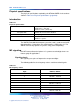
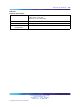
Connecting to the por ts
External devices are connected to the SDI/DCH card by the following:
•
the NTAK19FB four-port SDI cable. This cable does not have to be
terminated at the cross connect terminal since it is equipped with
connectors.
•
the NE-A25-B cable. Terminate the NE-A25-B cable at the cross
connect terminal. Tables Table 339 "NTAK02 pinouts - Port 0 at the
cross-connect terminal" (page 851) through Table 342 "NTAK02
connections at the cross-connect terminal - Port 3" (page 852) give
the pinouts for the SDI/DCH card.
Nortel Communication Server 1000
Circuit Card Reference
NN43001-311 01.04 Standard
Release 5.0 23 May 2008
Copyright © 2003-2008, Nortel Networks
.