
Computer Hardware Installation Guide

Configuring the QSDI paddle board 827
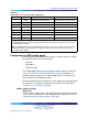
Table 323
NT8D41BA address switch settings
SW15
Port 1 Port 2
Switch settings
SW16
Port 3 Port 4 1* 2
+
34
5
6
7
8
01
E X off off off off off off
Device
23
E X off off off off off
on
4
5
E X off off off off
on
off
pair
6
7
E X off off off off
on on
89
E X off off off
on
off off
addresses
10 11
E X off off off
on
off
on
12 13
E X off off off
on on
off
14 15
E X off off off
on on on
* To enable ports 1 and 2, set SW15 position 1 to ON. To enable ports 3 and 4, set SW16 position 1
to ON.
+
For each X, the setting for this switch makes no difference, because it is not used.
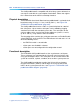
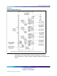
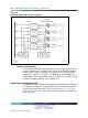
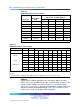
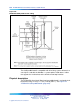
DTE/DCE/Fiber mode
Each serial port can be configured to connect to a terminal (DTE
equipment), a modem (DCE equipment), or a Fiber Superloop Network
card. Instructions for setting the switches SW2, SW3, SW4, SW5, SW6,
SW7, SW8, and SW9 are shown in Table 324 "NT8D41BA DTE/DCE/Fiber
switch settings" (page 827). Figure 270 "NT8D41BA QSDI paddle board"
(page 823) shows the location of these switches on the paddleboard.
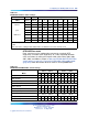
Table 324
NT8D41BA DTE/DCE/Fiber switch settings
Port 1 — SW 3 Port 1 — SW 2
Mode 1 2 3 456123456
DTE (terminal)
on on on
off
on
off off
on
off
on
off
on
DCE (modem) off off off
on
off
on on
off
on
off
on
off
NT1P61 (Fiber)
on on on on on
off
on on on
off
on
off
Port 2 — SW 5 Port 2 — SW4
DTE (terminal)
on on on
off
on
off off
on
off
on
off
on
DCE (modem) off off off
on
off
on on
off
on
off
on
off
NT1P61 (Fiber)
on on on on on
off
on on on
off
on
off
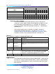
Port 3 — SW 7 Port 3 — SW 6
DTE (terminal)
on on on
off
on
off off
on
off
on
off
on
DCE (modem) off off off
on
off
on on
off
on
off
on
off
Nortel Communication Server 1000
Circuit Card Reference
NN43001-311 01.04 Standard
Release 5.0 23 May 2008
Copyright © 2003-2008, Nortel Networks
.