
Computer Hardware Installation Guide

826 NT8D41BA Quad Serial Data Interface Paddle Board
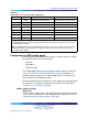
Table 321
NT8D41BA baud rate switch settings
SW13 (port 1), SW10 (port 2),
SW11 (port 3), SW12 (port 4)
Baud rate
Baud Clock
(kHz) 1 2 3 4
150 2.40
on
off
on on
300 4.80
on on
off
on
600 9.60
on
off off
on
1,200 19.20
on on on
off
2,400 38.40
on
off
on
off
4,800 76.80
on on
off off
9,600 153.60
on
off off off
19,200*
307.20
on on on on
* For future use.
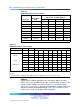
Table 322
NT8D41BA address switch settings
SW15
Port 1 Port 2
Switch settings
SW16
Port 3 Port 4 1* 2
+
34
5
6
7
8
01
E X off off off off off off
Device
23
E X off off off off off
on
4
5
E X off off off off
on
off
pair
6
7
E X off off off off
on on
89
E X off off off
on
off off
addresses
10 11
E X off off off
on
off
on
12 13
E X off off off
on on
off
14 15
E X off off off
on on on
* To enable ports 1 and 2, set SW15 position 1 to ON. To enable ports 3 and 4, set SW16 position 1
to ON.
+
For each X, the setting for this switch makes no difference, because it is not used.
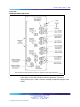
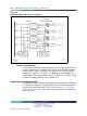
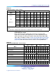
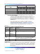
Address
Switch SW15 or SW16 and logic on the card always address the four
UARTs using a pair of addresses: 0 and 1, 2 and 3 through 14 and 15. The
settings for both switches are shown in Table 323 "NT8D41BA address
switch settings" (page 827). To avoid system problems, switches SW15 and
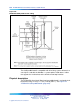
SW16 must not be configured identically. Figure 270 "NT8D41BA QSDI
paddle board" (page 823) displays SW15 and SW16.
Nortel Communication Server 1000
Circuit Card Reference
NN43001-311 01.04 Standard
Release 5.0 23 May 2008
Copyright © 2003-2008, Nortel Networks
.