
Computer Hardware Installation Guide

Configuring the SDI paddle board 815
Configuring the SDI paddle board
Configuring the SDI paddle board to work in a Meridian 1 system consists of
setting these option switches for each serial port:
• Port address
•
Baud rate
•
DTE/DCE/Fiber mode
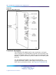
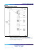
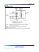
The SDI paddle board has seven option switches, SW 2–8. Figure 268 "SDI
paddle board option switch locations" (page 817) identifies the location of
option switches on the SDI paddle board. Instructions for setting these
switches are in the section that follows.
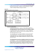
Once the board has been installed, the system software must be configured
to recognize it. Instructions for doing this are found in ""Software service
changes" (page 808)".
Option switch settings
Address
Address select switch SW4 and logic on the card always address the two
UARTs using a pair of addresses: 0 and 1, 2 and 3 through 15 and 16. The
settings for this switch are shown in Table 316 "SDI paddle board address
switch settings" (page 815).
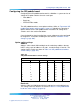
Table 316
SDI paddle board address switch settings
Address
Switch SW4
Port 1 Port 2 1 2 3 4
01
off
on on on
23
off
on on
off
4
5
off
on
off
on
6
7
off
on
off off
89
off off
on on
10 11
off off
on
off
12 13
off off off
on
14 15
off off off off
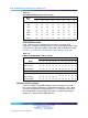
Baud rate
Switches SW2 and SW3 determine the baud rate for each individual port.
The settings for these switches are shown in Table 317 "SDI paddle board
baud rate switch settings" (page 816).
Nortel Communication Server 1000
Circuit Card Reference
NN43001-311 01.04 Standard
Release 5.0 23 May 2008
Copyright © 2003-2008, Nortel Networks
.