
Computer Hardware Installation Guide

806 NT8D41AA Serial Data Interface Paddle Board
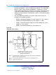
Once the board has been installed, the system software must be configured
to recognize it. Instructions for doing this are found in "Software service
changes" (page 808)".
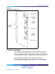
Option switch settings
Address
Address select switch SW4 and logic on the card always address the two
UARTs using a pair of addresses: 0 and 1, 2 and 3 through 15 and 16. The
settings for this switch are shown in Table 312 "SDI paddle board address
switch settings" (page 806).
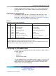
Table 312
SDI paddle board address switch settings
Address
Switch SW4
Port 1 Port 2 1 2 3 4
01
off
on on on
23
off
on on
off
4
5
off
on
off
on
6
7
off
on
off off
89
off off
on on
10 11
off off
on
off
12 13
off off off
on
14 15
off off off off
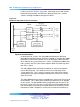
Baud rate
Switches SW2 and SW3 determine the baud rate for each individual port.
The settings for these switches are shown in Table 313 "SDI paddle board
baud rate switch settings" (page 806).
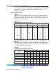
Table 313
SDI paddle board baud rate switch settings
Port 1 - SW2 Port 2 - SW3
Baud
rate
12341234
150
off off
on on
off off
on on
300
off
on
off
on
off
on
off
on
600
off off off
on
off off off
on
1200
off
on on
off off
on on
off
2400
off off
on
off off off
on
off
4800
off
on
off off off
on
off off
9600
off off off off off off off off
Nortel Communication Server 1000
Circuit Card Reference
NN43001-311 01.04 Standard
Release 5.0 23 May 2008
Copyright © 2003-2008, Nortel Networks
.