
Computer Hardware Installation Guide

Connector pin assignments 781
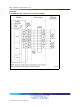
The E and M Trunk card brings the four analog trunks to the backplane
through a 160-pin connector shroud. External equipment connects to the
card at the back of the Media Gateway and Media Gateway Expansion
using a 25-pin connector. Telephone trunks connect to the E and M Trunk
card at the MDF using a wiring plan similar to that used for line cards.
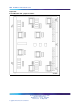
A typical connection example is shown in Figure 253 "E and M Trunk card -
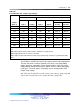
typical cross connection example" (page 782). A list of the connections to
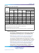
the E and M Trunk card in the various 2-wire modes is shown in Table 299
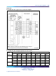
"E and M Trunk card - backplane pinouts for 2-wire modes" (page 780).A
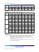
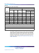
list of the connections to the E and M Trunk card in the various 4-wire modes
is shown in Table 300 "E and M Trunk card - backplane pinouts for 4-wire
modes" (page 780). See Communication Server 1000M and Meridian 1
Large System Installation and Configuration (NN43021-310) for complete
I/O connector information and wire assignments for each tip/ring pair.
Nortel Communication Server 1000
Circuit Card Reference
NN43001-311 01.04 Standard
Release 5.0 23 May 2008
Copyright © 2003-2008, Nortel Networks
.