
Computer Hardware Installation Guide

Connector pin assignments 777
Telephone trunks connect to the E and M Trunk card at the MDF using a
wiring plan similar to that used for line cards.
A typical connection example is shown in Figure 252 "E and M Trunk card
- typical cross connection example" (page 779). A list of the connections
to the E and M Trunk card in the various 2-wire modes is shown in Table
297 "E and M Trunk card - backplane pinouts for 2-wire modes" (page 777).
A list of the connections to the E and M Trunk card in the various 4-wire
modes is shown in Table 298 "E and M Trunk card - backplane pinouts for
4-wire modes" (page 777).
See Communication Server 1000M and Meridian 1 Large System
Installation and Configuration (NN43021-310) for complete I/O connector
information and wire assignments for each tip/ring pair.
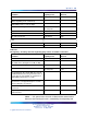
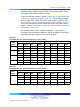
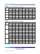
Table 297
E and M Trunk card - backplane pinouts for 2-wire modes
2-wire Paging Mode 2-wire Type I Mode
Trunk
Number Pin Signal Pin Signal Pin Signal Pin Signal
12B Tip 12A Ring 12B Tip 12A Ring
0
15B A 15A PG 14B E 14A M
16B Tip 16A Ring 16B Tip 16A Ring
1
19B A 19A PG 18B E 18A M
62B Tip 62A Ring 62B Tip 62A Ring
2
65B A 65A PG 64B E 64A M
66B Tip 66A Ring 66B Tip 66A Ring
3
69B A 69A PG 48B E 68A M
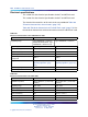
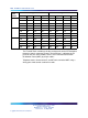
Table 298
E and M Trunk card - backplane pinouts for 4-wire modes
4-wire Type I Mode 4-wire Type II Mode
Trunk
Number Pin Signal Pin Signal Pin Signal Pin Signal
12B TA 12A TB 12B TA 12A TB
13B RA 13A RB 13B RA 13A RB
14B E 14A M 14B EA 14A EB
0
15B ECG 15A ESCG 15B MA 15A MB
Nortel Communication Server 1000
Circuit Card Reference
NN43001-311 01.04 Standard
Release 5.0 23 May 2008
Copyright © 2003-2008, Nortel Networks
.