
Computer Hardware Installation Guide
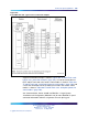

772 NT8D15 E and M Trunk card
Electrical specifications
This section lists the electrical specifications for the E and M Tr unk card.
This section lists the electrical specifications for the E and M Tr unk card.
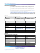
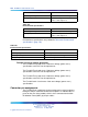
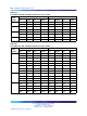
The electrical characteristics of all trunk circuits are provided in Table 286
"Electrical characteristics of trunk cards" (page 772).
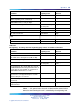
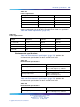
Table 285 "Electrical characteristics of E and M Trunk cards" (page 772) lists
the electrical characteristics of the trunk interface on the E and M Trunk card.
Table 285
Electrical characteristics of E and M Trunk cards
Characteristic
4-wire trunk 2-wire trunk
Signaling range Type I#160;#160; 150 ohms
#160;#160; #160;#160; Type
II#160;#160; 300 ohms loop
Type I#160;#160; 150 ohms
Signaling type Type I, Type II Type I
Far-end battery –42 to –52.5 V dc –42 to –52.5 V dc
Near-end battery –42.75 to –52.5 V dc –42.75 to –52.5 V dc
Ground potential difference ±10 V dc ±10 V dc
Line leakage between E lead
and ground
ˇ
S20K
3
/4
ˇ
S20K
3
/4
Effective loss See pad table (Table 306 "Pad
switching algorithm" (page
791))
See pad table (Table 306 "Pad
switching algorithm" (page 791))
Terminating impedance 600 ohms 600 ohms
Balance impedance N/A 600 ohms
Table 286
Electrical characteristics of trunk cards
Characteristic
DID Trunk
CO trunk
Nominal impedance 600 or 900 ohms, (selected by
software)
600 or 900 ohms, (selected by
software)
Signaling range 2450 ohms 1700 ohms
Signaling type Loop Ground or loop start
Far-end battery -42 to -52.5 V -42 to -52.5 V
Near-end battery N/A -42.75 to -52.5 V
Minimum loop current N/A 20 mA
Ground potential difference + 10 V + 3 V
Nortel Communication Server 1000
Circuit Card Reference
NN43001-311 01.04 Standard
Release 5.0 23 May 2008
Copyright © 2003-2008, Nortel Networks
.